W2940305 Rev 07 8/2019 Dover Fueling Solutions 115
T568B
T568
1234
5
678
Pair 2
Pair 3
Pair 2
Pair 3
876543
21
Ora
Ora/Wht
Grn
Grn/Wht
Grn/Wht
Grn
Ora
Ora/Wht
Configuration
Side A R2 iX Board Side B R2 iX Board
Single-Sided Terminated
Dual-Sided Unterminated Terminated
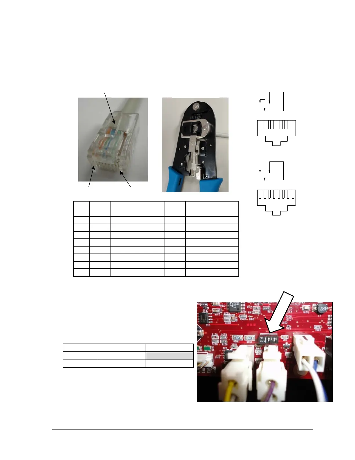
Termination After the Ethernet cable has been pulled into the dispenser, it must be
terminated with an RJ45 jack. Two wire schemes are shown below. Most
applications use T568A. Either wiring scheme can be used as long as the
same scheme is used at both ends of the cable. RJ45 connectors and
crimpers can be purchased at hardware and electronic chain stores.
Pin
T5
A
Pair T568A Color
T5
B
Pair T568B Color
13
green striped
2
orange striped
23
green
2
orange
32
orange striped
3
green striped
41 1
51 1
62
orange
3
green
74 4
84 4
H.4 iX Fleet Board Setup
Set the communication loop termination on
the R2 board according to the following iX
configuration chart below using the switches
shown in Figure 35.
Terminated – Switches placed toward center
of iX R2 board.
Unterminated – Switches placed towards
edge of iX R2 board.
Pin 1 Pin 8
Cli
on to
Crimping Tool
 Loading...
