W2940305 Rev 07 8/2019 Dover Fueling Solutions 21
In mm
In
2
mm
2
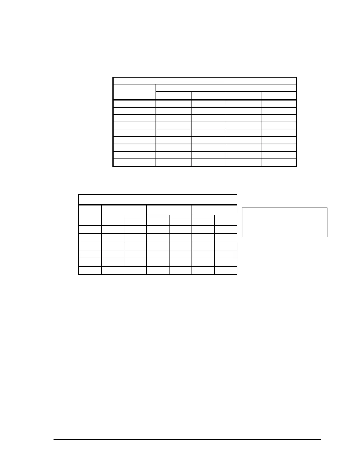
18 .090 2.29 .007 4.1
14 .118 2.95 .011 6.8
12 .135 3.43 .014 9.2
10 .169 4.29 .022 14.5
8 .216 5.49 .037 23.7
6 .259 6.60 .053 34.2
4 .331 8.41 .086 55.5
3 .359 9.14 .102 65.6
2 .394 10.01 .122 78.7
Wire Gauge
Diameter Square Area
THHN/THWN Wire Areas
in mm
in
2
mm
2
in
2
mm
2
1
/
2
"
.629 16 .311 201 .078 50
3
/
4
"
.826 21 .536 346 .134 86
1" 1.063 27 .887 572 .222 143
1
1
/
4
"
1.378 35 1.491 962 .373 240
1
1
/
2
"
1.614 41 2.046 1320 .512 330
2" 2.087 53 3.421 2207 .855 552
Trade Size Conduit Square Area
Trade
Size
Conduit
Internal Diameter Square Area 25% Fill Area
The following charts are provided as a guide to help determine the proper conduit sizes.
Step 1 Determine the square area for each wire by looking up the desired wire gauge
below and writing down the corresponding square area from the Square Area
column. Calculate the total area by adding the square area for each of the
wires.
Step 2 In the 25% Fill Area column below, find the square area that is closest to,
without exceeding, the calculated total area. The value listed on the same row
in the Trade Size Conduit column is the diameter of the required conduit.
3.4 Gasoline & Diesel Hose and Accessories Installation
3.4.1 General
Hose assemblies should be U.L. listed and installed in accordance with the
manufacturer’s instructions.
Install the hose assembly after the dispenser is installed.
o To ensure a proper joint, wash all cutting oil off the threads and use a U.L. listed
gasoline-resistant pipe joint sealing compound.
o Place the compound on male threads only; be careful not to get any excess
compound on the inside of the fittings.
o Install the fixed end of the hose to the dispenser outlet; secure according to the
instructions of the sealing compound and hose manufacturer.
o Install the nozzle, and other hose accessories – swivels, breakaways, etc. – on the
hose according to the manufacturer’s instructions.
NFPA code requires a listed emergency breakaway device, designed to retain liquid on
both sides of the breakaway point, to be installed on each hose. These devices must be
installed and maintained per the manufacturer’s instructions. Refer to your state and local
codes for breakaway device requirements that apply to your installation.
The calculated conduit size
may need to be increased to
allow for long runs or a large
number of bends
 Loading...
