W2940305 Rev 07 8/2019 Dover Fueling Solutions 59
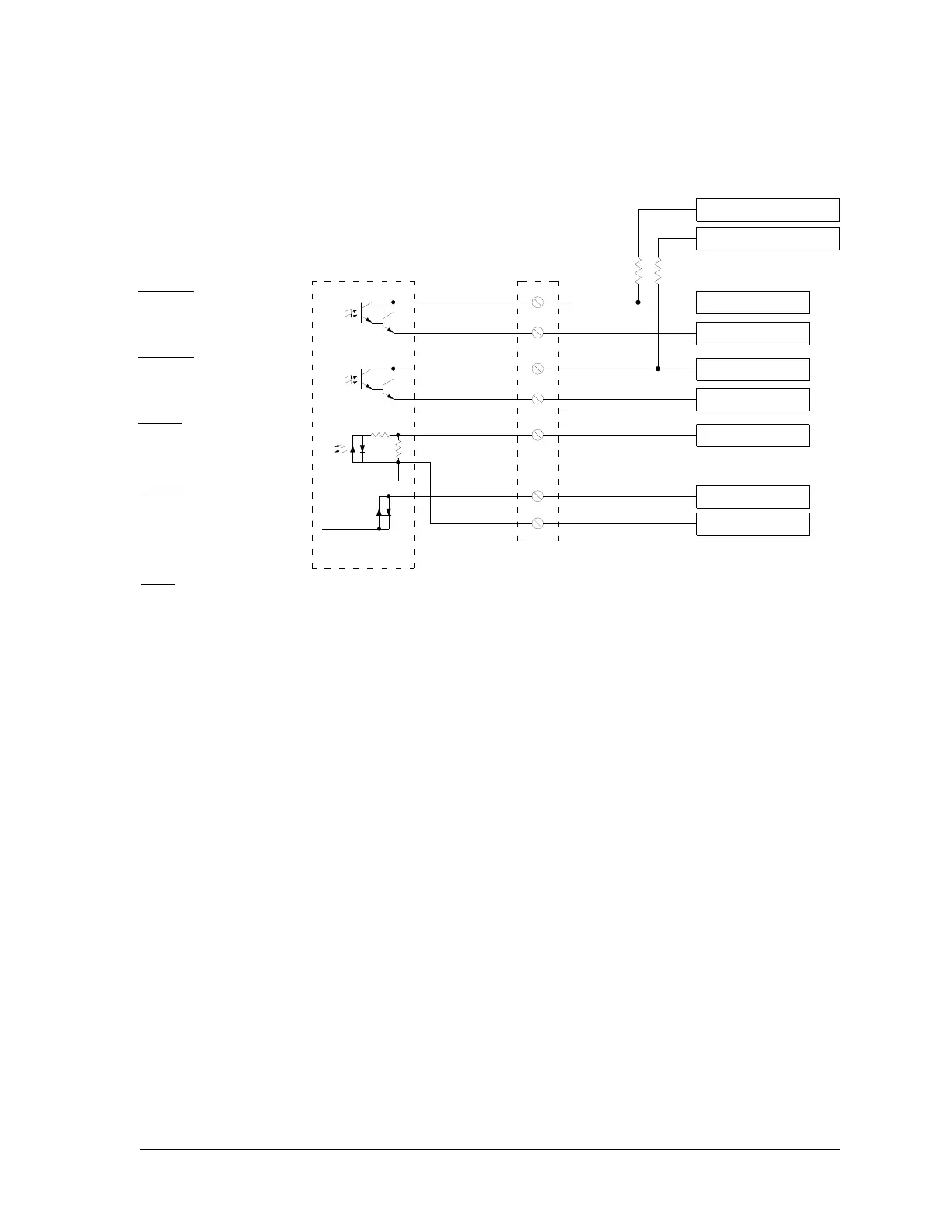
Field Connection Ratings
PUL A1X+
PUL A1X-
PUL A1Y-
PUL A1Y+
AUTH A1
RESET A1
NEUT
VAC Neut
Opto
SS
Relay
1
2
3
4
5
6
7
VAC Hot
Pulse Output
Side A, Hose 1, Channel X
Open Collector
Max Voltage 24V
Max Current 75ma
Pulse Output
Side A, Hose 1, Channel Y
Open Collector
Max Voltage 24V
Max Current 100ma
Auth Input
Side A, Hose 1
Opto-Coupler
Voltage 120VAC or 240VAC
Typ Current 170ma(120) or 55ma(240)
Reset Output
Side A, Hose 1
Solid State Relay
Voltage 120VAC or 240VAC
Max Current 1A(120) or 0.5A(240)
Pulse to Primary
Control System
Pulse to Secondary
Monitoring System
Ground from Secondary
Monitoring System
Ground from Primary
Control System
V+ from Primary Control
System (24V Max)
V+ from Secondary Monitoring
System (24V Max)
AC Auth Signal from
Primary Control System
AC Neutral for Primary
Control System
AC Reset Signal to
Primary Control System
Pull-up resistors
not supplied
with dispenser
Red
Red Str/White
Brown
Brown Str/White
Black
White
Orange
Pulse Output
Terminal Block
Pulse Output Board
Side A
Notes:
1. 120 VAC systems utilize Pulse Output Board WU016048-0001. 240 VAC systems utilize Pulse Output Board
WU016048-0002.
2. The Control and Monitoring systems should be powered from the same breaker panel as the dispenser so that they
share a common Neutral.
3. Auth Input: Some Fuel Management Systems use solid state relays which can supply a low level voltage while in the
"Off" position. In some cases, the voltage can be high enough to cause false tripping of the Auth Input. Always verify
that any voltage present on this line during the "Off" position is not sufficient to turn on the Auth relay or to cause it to
chatter. If such a condition does exist, an additional load may need to be placed across the Auth Input to reduce
the voltage.
4. Reset Output: Some Fuel Management Systems cannot sense voltage and sense current for the reset output
(e.g. OPW PetroVend K800, PetroVend System2). Check the installation requirements of the fuel management system
to determine if they require, and supply, additional components such as a voltage to current sense convertor.
Appendix C: Pulse Output Interface
C.1 Pulse Output Interface Wiring Diagram
 Loading...
