58 Dover Fueling Solutions W2940305 Rev 07 8/2019
Grounding
See Note 5
Subm Relay Control X
To Anti-Siphon Solenoid Valve
See Note 7
Control Power
Hot
Neut
To Subm Relay Controls for
Submersible Pump
See Note 6
Subm Relay Control X
Ethernet
Electronic Head
Black
Control Power (Hot)
12
3
White/Red Subm Relay Control X
4
56
7
White
Control Power (Neut)
8
Earth GroundGreen
9
Brown Data +
10
Violet Data -
11
Yellow Data +
12
Violet Data -
Dispenser
CAT (Opt.)
Ethernet
Switch
Pump Direct Drive (In)
Black
Brown
Pump Direct Drive (Out)
Neut
Hot
Pump Direct
Drive (Optional)
See Note 8
Pump Direct Drive
To Pump
See Note 8
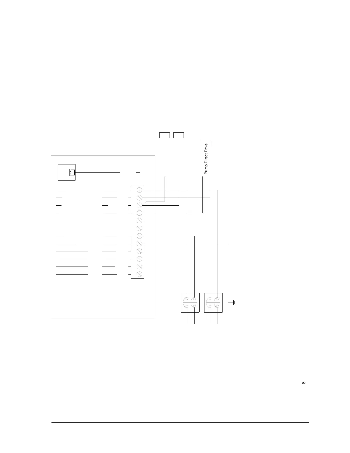
B.2 Wiring Diagram: All Models
Notes:
1. All equipment to be installed in accordance with all applicable local, state, and federal codes, including, but not limited to, the National Electrical Code (NFPA
70), NFPA 30, and the Automotive and Marine Service Station Code (NFPA 30A).
2. For wiring connections, use wires rated at least 90
o
C, 600V, Gas & Oil Resistant.
3. See wire size chart for proper gauge of the wires.
4. For full details of DFS control systems interconnections see the manual provided with the Wayne pump control system or Wayne card processing system.
5. Attach the ground to the Terminal Block ground screw provided.
6. A submersible control relay is required to control the submersible pump.
7. If this dispenser is used with an aboveground tank, a solenoid valve mounted on top of the tank must be used. Use the submersible control line to control the
valve. Valve voltage rating must match that of the dispenser (120 or 240 VAC) and is limited 18 Watts.
8. Dispensers equipped with the Pump Direct Drive Relay option can directly control pumps up to 1 HP, with a maximum current of 14 Amps at 120 VAC or 7
Controls only 1 leg to the pump.
 Loading...
