20 Dover Fueling Solutions W2940305 Rev 07 8/2019
Current 1'-25' 26'-50' 51'-75' 76'-100' 101'-150' 151'-200' 201'-250' 251'-300'
2.5 A1414141414141414
5.0 A1414141414141412
7.5 A1414141414121210
10.0 A1414141412121010
Recommended Wire Size (AWG)
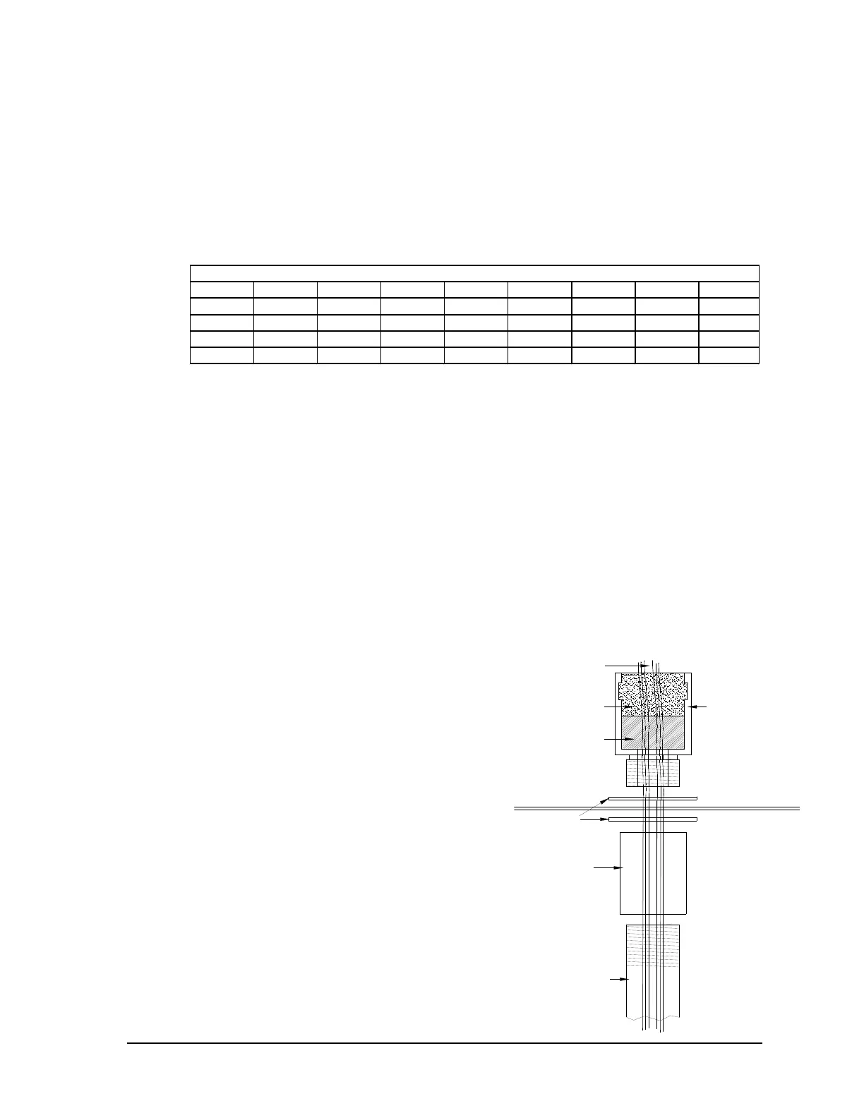
Vapor Barrier
Washer
Coupler
3/4" Conduit
Conduit
Fitting
Potting
Material
Cable &
Wires
Separator
Gasket
3.3.6 Wire Type
All wiring should be UL-Listed, rated for a minimum 90
0
C (194
0
F), 600V, and gasoline
and oil-resistant stranded wire.
All AC wire terminations must be made to the standard and optional terminal blocks as
applicable. Make sure that any unused conduit entry openings are properly plugged.
3.3.6.1 Wire Size
For the Control Wiring, the size of the wire used should be determined by the power
requirements of the dispenser and the length of run from the breaker panel.
For the submersible control line going to submersible starter relays, 14 AWG wire is
recommended for most applications. The wire gauge for the submersible pump should
be determined by the size of the motor and the length of the run according to the
manufacturer’s installation instructions and NFPA 70A.
The wire size for the pulse output must be 18 AWG. The authorization and reset lines
must be no smaller than 18 AWG. Reference the installation instructions of the fuel
control system manufacturer regarding running DC wires with AC wires and the
necessary wire specifications (shielding, etc.).
3.3.7 Conduit
Use UL Listed threaded, rigid, metal conduit and properly sealed connectors. Threaded
connections must be drawn up tight and have a minimum of five threads engaged.
Do not use flexible conduit or knockout boxes.
When connecting to a fuel control system, consult the manufacturer’s instructions for
conduit requirements for AC and DC lines.
The dispenser is provided with a minimum of
two or three ¾” conduit assemblies that are
used to route the field wiring (including the
optional motor wiring) into the head assembly.
Two are provided for standard dispensers and
an extra (the third assembly) is provided with
dispensers equipped with a Pulse Output
option or an iX Fleet terminal. These conduit
assemblies include a conduit fitting (for
potting), 2 washers, a coupling, separator
gasket and a piece of ¾” conduit. The field
wiring must be potted in the fitting provided as
it passes through dispenser’s vapor barrier.
The wires should be separated with the
separator gasket to allow the potting material to
surround each of the wires. The total cross-
section area of the wiring feeding through one
of the conduit fittings is not to exceed 0.092 sq.
in. or 59.6 sq. mm.
 Loading...
