70 Dover Fueling Solutions W2940305 Rev 07 8/2019
TB5 or TB6
Data
Out
Data
In
+
--
+
563421
TB5 or TB6
12 4
365
+
--
+
Data
In
Data
Out
Current
Loop B
Current
Loop A
Bypass
Auto
Auto
Bypass
65
4
3
21
8
7
6
5
4
3
2
1
8
7
6
5
4
3
2
1
Data
Out
Data
In
Data
Out
Data
In
+
--
++
--
+
+
-
-
+
+
-
-
+
+
-
-
+
+
-
-
+
+
-
-
+
+
-
-
+
1
2
3
4
5
6
7
8
8
7
6
5
4
3
2
1
Current
Loop B
Current
Loop A
TB6
TB5
563
421
TB2
TB4
TB3
TB1
+
-
-
+
+
-
-
+
Dispenser
Dispenser
Dispenser
Dispenser
Dispenser
Dispenser
Dispenser
Dispenser Dispenser
Dispenser
Dispenser
Dispenser
Dispenser
Dispenser
Dispenser
Dispenser
1
2
3
4
5
6
7
8
16
15
14
13
12
11
10
9
TB2
Data Distribution Cabinet
HyperPIB
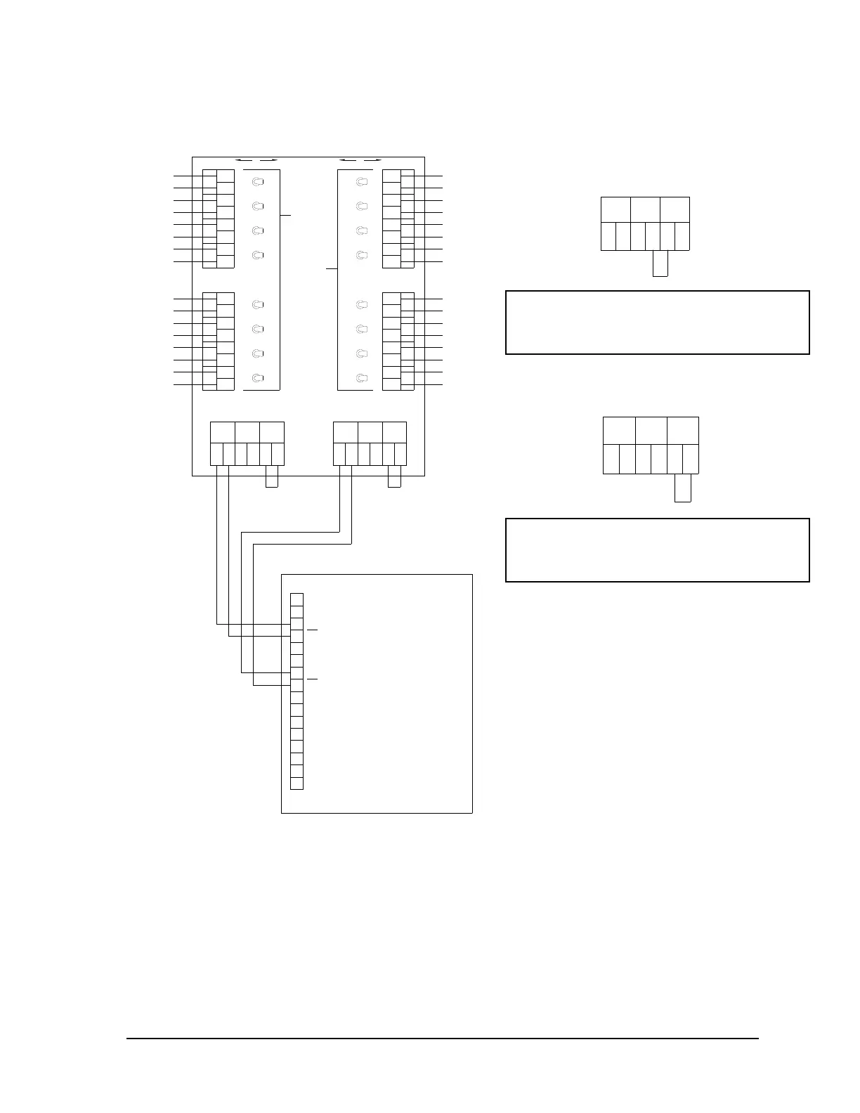
C.7 Wiring Using One Data Distribution Cabinet (Up to 16 dispensers)
Notes:
1. Two Current Loops are provided for communication to the dispensers from the HyperPIB.
Evenly distribute the dispenser loads across both loops in the Data Distribution Cabinet.
2. All unused dispenser positions in the Date Distribution Cabinet should be jumpered in the
cabinet with the switch placed in the “Auto” position. This practice reduces the overall
load on the loop.
3. Each loop in this configuration is limited to 8 dispensers and a total wire length of 1800
feet. This length of 1800 feet includes the distance between the HyperPIB and the Data
Distribution Cabinet as well as the distance between each dispenser and the Data
Distribution Cabinet.
4. See the TB5/TB6 jumper requirements for each loop according to the drawing above.
TB5 is associated with Loop A and TB6 is associated with Loop B.
Jumper positions 4 & 5 for 4 or less
dispensers per loop OR cumulative distances
of less than 150 feet per loop.
Jumper positions 5 & 6 for 5 or more
dispensers per loop OR cumulative distances
of 150 feet or greater per loop.
 Loading...
