GE Power Management
489 Generator Management Relay 4-75
4 SETPOINT PROGRAMMING 4.13 489 TESTING
4
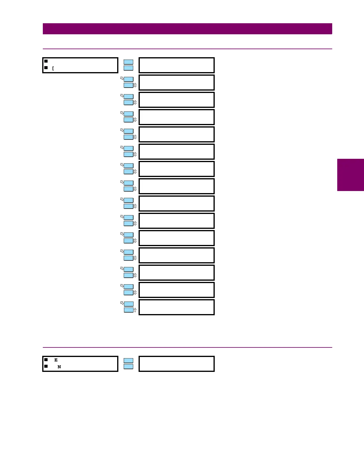
4.13.3 FAULT SETUP
The values entered under Fault Values will be substituted for the measured values in the 489 when the
SIMULATION MODE
is
"Simulate Fault".
4.13.4 TEST OUTPUT RELAYS
The test output relays setpoint may be used during startup or testing to verify that the output relays are functioning cor-
rectly. The output relays can be forced to operate only if the generator is offline, no current is measured, and there are no
trips or alarms active. If any relay is forced to operate, the relay will toggle from its normal state when there are no trips or
alarms to its operated state. The appropriate relay indicator will illuminate at that time. Selecting "Disabled" places the out-
put relays back in service. If the 489 measures current or control power is cycled, the force operation of relays setpoint will
automatically become disabled and the output relays will revert back to their normal states.
If any relay is forced, the 489 in Service indicator will flash, indicating that the 489 is not in protection mode.
FAULT SETUP
[ENTER] for more
FAULT Iphase
OUTPUT: 0.00 x CT
Range: 0.00 to 20.00
×
CT in steps of 0.01
FAULT VOLTAGES
PHASE-N: 1.00 x Rated
Range: 0.00 to 1.50
×
Rated in steps of 0.01
Entered as a phase-to-neutral quantity.
FAULT CURRENT
LAGS VOLTAGE: 0°
Range: 0 to 359° in steps of 1
FAULT Iphase
NEUTRAL: 0.00 x CT
Range: 0.00 to 20.00
×
CT in steps of 0.01
180° phase shift with respect to Iphase OUTPUT
FAULT CURRENT
GROUND: 0.00 x CT
Range: 0.00 to 20.00
×
CT in steps of 0.01
CT is either XXX:1 or 50:0.025
FAULT VOLTAGE
NEUTRAL: 0 Vsec
Range: 0.0 to 100.0 Vsec in steps of 0.1
Fundamental value only in secondary volts
FAULT STATOR
RTD TEMP: 40°C
Range: –50 to 250°C in steps of 1
FAULT BEARING
RTD TEMP: 40°C
Range: –50 to 250°C in steps of 1
FAULT OTHER
RTD TEMP: 40°C
Range: –50 to 250°C in steps of 1
FAULT AMBIENT
RTD TEMP: 40°C
Range: –50 to 250°C in steps of 1
FAULT SYSTEM
FREQUENCY: 60.0 Hz
Range: 5.0 to 90.0 Hz in steps of 0.1
FAULT ANALOG
INPUT 1: 0%
Range: 0 to 100% in steps of 1
FAULT ANALOG
INPUT 2: 0%
Range: 0 to 100% in steps of 1
FAULT ANALOG
INPUT 3: 0%
Range: 0 to 100% in steps of 1
FAULT ANALOG
INPUT 4: 0%
Range: 0 to 100% in steps of 1
TEST OUTPUT RELAYS
[ENTER] for more
FORCE OPERATION OF
RELAYS: Disabled
Range: Disabled, R1 Trip, R2 Auxiliary, R3 Auxiliary, R4
Auxiliary, R5 Alarm, R6 Service, All Relays, No
Relays
MESSAGE
ESCAPE
MESSAGE
ESCAPE
MESSAGE
ESCAPE
MESSAGE
ESCAPE
MESSAGE
ESCAPE
MESSAGE
ESCAPE
MESSAGE
ESCAPE
MESSAGE
ESCAPE
MESSAGE
ESCAPE
MESSAGE
ESCAPE
MESSAGE
ESCAPE
MESSAGE
ESCAPE
MESSAGE
ESCAPE
MESSAGE
ESCAPE
 Loading...


