3-2 489 Generator Management Relay
GE Power Management
3.1 OVERVIEW 3 OPERATION
3
3.1.2 DISPLAY
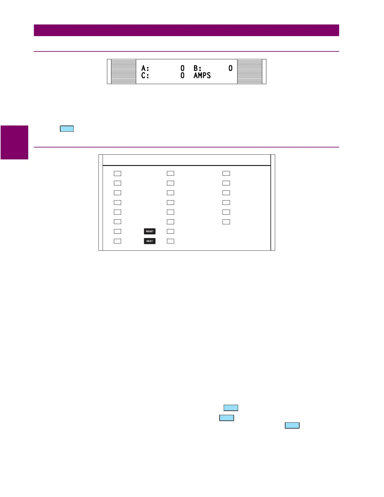
Figure 3–2: 489 DISPLAY
All messages appear on a 40-character vacuum fluorescent display for visibility under poor lighting conditions. Messages
are in plain English and do not require the aid of an instruction manual for deciphering. When the user interface is not being
used, the display defaults to the user-defined status messages. Any trip or alarm automatically overrides the default mes-
sages and is immediately displayed.
Press the key for 2 seconds to initiate a lamp test.
3.1.3 LED INDICATORS
Figure 3–3: 489 LED INDICATORS
There are three groups of LED indicators: 489 STATUS, GENERATOR STATUS, and OUTPUT RELAYS.
a) 489 STATUS LED INDICATORS
•489 IN SERVICE: Indicates that control power is applied, all monitored input/output and internal systems are OK, the
489 has been programmed, and is in protection mode, not simulation mode. When in simulation or testing mode, the
LED indicator will flash.
• SETPOINT ACCESS: Indicates that the access jumper is installed and passcode protection has been satisfied. Set-
points may be altered and stored.
• COMPUTER RS232: Flashes when there is any activity on the RS232 communications port. Remains on continuously
if incoming data is valid.
• COMPUTER RS485: Flashes when there is any activity on the RS485 communications port. Remains on continuously
if incoming data is valid and intended for the slave address programmed in the relay.
• AUXILIARY RS485: Flashes when there is any activity on the communications port. Remains on continuously if
incoming data is valid and intended for the slave address programmed in the relay.
• ALT. SETPOINTS: Flashes when the alternate setpoint group is being edited and the primary setpoint group is active.
Remains on continuously if the alternate setpoint group is active. The alternate setpoint group feature is enabled as
one of the assignable digital inputs. The alternate setpoints group can be selected by setting the
S3 DIGITAL INPUTS /
DUAL SETPOINTS / ACTIVATE SETPOINT GROUP
setpoint to "Group 2".
• RESET POSSIBLE: A trip or latched alarm may be reset. Pressing the key clears the trip/alarm.
• MESSAGE: Indicator flashes when a trip or alarm occurs. Press the key to scroll through the diagnostic mes-
sages. Remains solid when setpoint and actual value messages are being viewed. Pressing the key returns the
display to the default messages.
HELP
489 STATUS GENERATOR STATUS OUTPUT RELAYS
R1 TRIP
R2 AUXILIARY
R3 AUXILIARY
R4 AUXILIARY
R5 ALARM
R6 SERVICE
BREAKER OPEN
BREAKER CLOSED
HOT STATOR
NEG. SEQUENCE
GROUND
LOSS OF FIELD
VT FAILURE
BREAKER FAILURE
489 IN SERVICE
SETPOINT ACCESS
COMPUTER RS232
COMPUTER RS485
AUXILIARY RS485
ALT. SETPOINTS
RESET
POSSIBLE
MESSAGE
NEXT
 Loading...


