GE Power Management
489 Generator Management Relay 4-39
4 SETPOINT PROGRAMMING 4.7 S6 VOLTAGE ELEMENTS
4
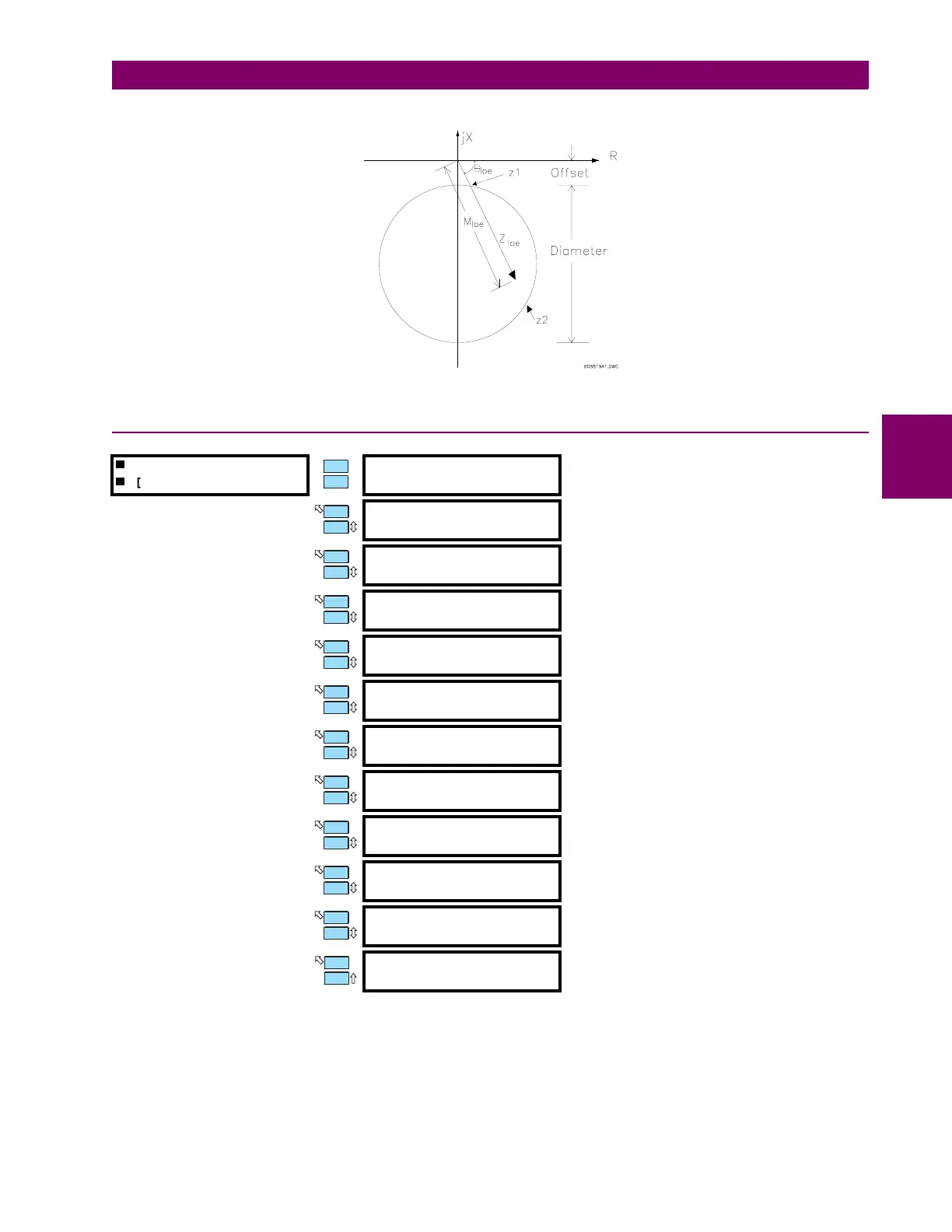
Figure 4–7: LOSS OF EXCITATION R-X DIAGRAM
4.7.10 DISTANCE ELEMENTS
The distance protection function (ANSI device 21) implements two zones of mho phase-to-phase distance protection (six
elements total) using the conventional phase comparator approach, with the polarizing voltage derived from the pre-fault
positive sequence voltage of the protected loop. This protection is intended as backup for the primary line protection. The
elements make use of the neutral-end current signals and the generator terminal voltage signals (see figure below), thus
providing some protection for internal and unit transformer faults. In systems with a delta-wye transformer (DY330°), the
appropriate transformations of voltage and current signals are implemented internally to allow proper detection of trans-
DISTANCE ELEMENT
[ENTER] for more
STEP UP TRANSFORMER
SETUP: None
Range: None, Delta/Wye
FUSE FAILURE
SUPERVISION: On
Range: On, Off
ZONE #1
TRIP: Off
Range: Off, Latched, Unlatched
ASSIGN ZONE #1 TRIP
RELAYS (1-4): 1---
Range: Any combination of Relays 1 to 4
ZONE #1
REACH: 10.0
Ω
sec
Range: 0.1 to 500.0
Ω
sec in steps of 0.1
ZONE #1
ANGLE: 75°
Range: 50 to 85° in steps of 1
ZONE #1 TRIP
DELAY: 0.4 s
Range: 0.0 to 150.0 s in steps of 0.1
ZONE #2
TRIP: Off
Range: Off, Latched, Unlatched
ASSIGN ZONE #2 TRIP
RELAYS (1-4): 1---
Range: Any combination of Relays 1 to 4
ZONE #2
REACH: 15.0
Ω
sec
Range: 0.1 to 500.0
Ω
sec in steps of 0.1
ZONE #2
ANGLE: 75°
Range: 50 to 85° in steps of 1
ZONE #2 TRIP
DELAY: 2.0 s
Range: 0.0 to 150.0 s in steps of 0.1
MESSAGE
ESCAPE
MESSAGE
ESCAPE
MESSAGE
ESCAPE
MESSAGE
ESCAPE
MESSAGE
ESCAPE
MESSAGE
ESCAPE
MESSAGE
ESCAPE
MESSAGE
ESCAPE
MESSAGE
ESCAPE
MESSAGE
ESCAPE
MESSAGE
ESCAPE
 Loading...


