B-4 489 Generator Management Relay
GE Power Management
B.1 STATOR GROUND FAULT PROTECTION APPENDIX B
B
B.1.4 GROUND DIRECTIONAL ELEMENT
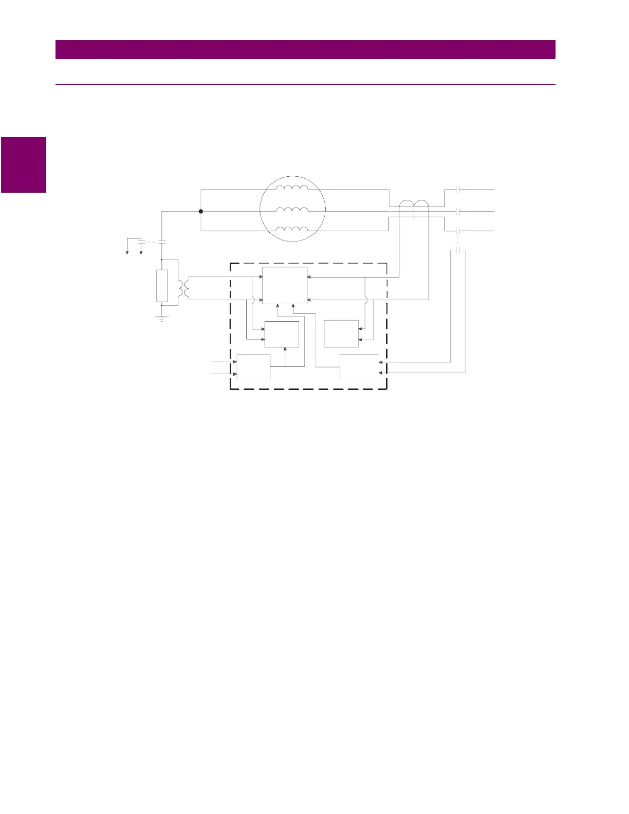
The 489 can detect internal stator ground faults using a Ground Directional element implemented using the
V
neutral
and the
ground current inputs. The voltage signal is obtained across the grounding impedance of the generator. The ground, or
zero sequence, current is obtained from a core balance CT, as shown below (due to CT inaccuracies, it is generally not
possible to sum the outputs of the conventional phase CTs to derive the generator high-side zero sequence current, for an
impedance-grounded generator).
Figure B–4: GROUND DIRECTIONAL ELEMENT CONCEPTUAL ARRANGEMENT
If correct polarities are observed in the connection of all signals to the relay, the
V
neutral
signal will be in phase with the
ground current signal. The element has been provided with a setting allowing the user to change the plane of operation to
cater to reactive grounding impedances or to polarity inversions.
This element’s normal "plane of operation" for a resistor-grounded generator is the 180° plane, as shown in Figure B–5:
GROUND DIRECTIONAL ELEMENT POLARITIES AND PLANE OF OPERATION, for an internal ground fault. That is, for
an internal stator-to-ground fault, the
V
o
signal is 180° away from the
I
o
signal, if the polarity convention is observed. If the
grounding impedance is inductive, the plane of operation will be the 270° plane, again, with the polarity convention shown
below. If the polarity convention is reversed on one input, the user will need to change the plane of operation by 180°.
The operating principle of this element is quite simple: for internal ground faults the two signals will be 180° out of phase
and for external ground faults, the two signals will be in phase. This simple principle allows the element to be set with a high
sensitivity, not normally possible with an overcurrent element.
The current pickup level of the element can be adjusted down to 0.05 × CT primary, allowing an operate level of 0.25 A pri-
mary if the 50:0.025 ground CT is used for the core balance. The minimum level of
V
neutral
at which the element will operate
is determined by hardware limitations and is internally set at 2.0 V.
Because this element is directional, it does not need to be coordinated with downstream protections and a short operating
time can be used. Definite time delays are suitable for this element.
GENERATOR
CORE
BALANCE
CT
BREAKER
Aux.
Contact
Grounding
Switch
To Relay
Grounding
Impedance
(Trans. &
Resistor)
Grounding
Switch
Aux. Cont.
G.S.
Status
Breaker
Status
Ground
O/C
Element
Isolating
Transformer
V
Input
neutral
Ground
Directional
Element
(or O/C)
489
Neutral
O/V
Element
Ground
Current
Input
Aux.
Breaker
GDECON2.CDR
 Loading...


