7-4 489 Generator Management Relay
GE Power Management
7.2 HARDWARE FUNCTIONAL TESTING 7 TESTING
7
7.2.3 GROUND (1A), NEUTRAL AND DIFFERENTIAL CURRENT ACCURACY
The specification for neutral, differential and 1 A ground current input accuracy is ±0.5% of 2 × CT. Perform the steps below
to verify accuracy.
1. Alter the following setpoints:
S2 SYSTEM SETUP\CURRENT SENSING\GROUND CT:
1A Secondary
S2 SYSTEM SETUP\CURRENT SENSING\GROUND CT RATIO:
1000:1
S2 SYSTEM SETUP\CURRENT SENSING\PHASE CT PRIMARY:
1000 A
S5 CURRENT ELEMENTS\PHASE DIFFERENTIAL\PHASE DIFFERENTIAL TRIP:
unlatched
S5 CURRENT ELEMENTS\PHASE DIFFERENTIAL\DIFFERENTIAL TRIP MIN. PICKUP:
0.1xCT
2. Note: the last two setpoints are needed to view the neutral and the differential current. The trip element will operate
when differential current exceeds 100 A.
3. Measured values should be ±10 A. Inject (
I
A
only) the values shown in the table below into one phase only and verify
accuracy of the measured values. View the measured values in:
A2 METERING DATA\CURRENT METERING
or press the key to view the current values when differential trip element is active.
7.2.4 NEUTRAL VOLTAGE (FUNDAMENTAL) ACCURACY
The specification for neutral voltage (fundamental) accuracy is ±0.5% of full scale (100 V). Perform the steps below to verify
accuracy.
1. Alter the following setpoints:
S2 SYSTEM SETUP\VOLTAGE SENSING\NEUTRAL VOLTAGE TRANSFORMER:
Yes
S2 SYSTEM SETUP\VOLTAGE SENSING\NEUTRAL V.T. RATIO:
10.00:1
S2 SYSTEM SETUP\GEN. PARAMETERS\GENERATOR NOMINAL FREQUENCY:
60 Hz
2. Measured values should be ±5.0 V. Apply the voltage values shown in the table and verify accuracy of the measured
values. View the measured values in:
A2 METERING DATA\VOLTAGE METERING
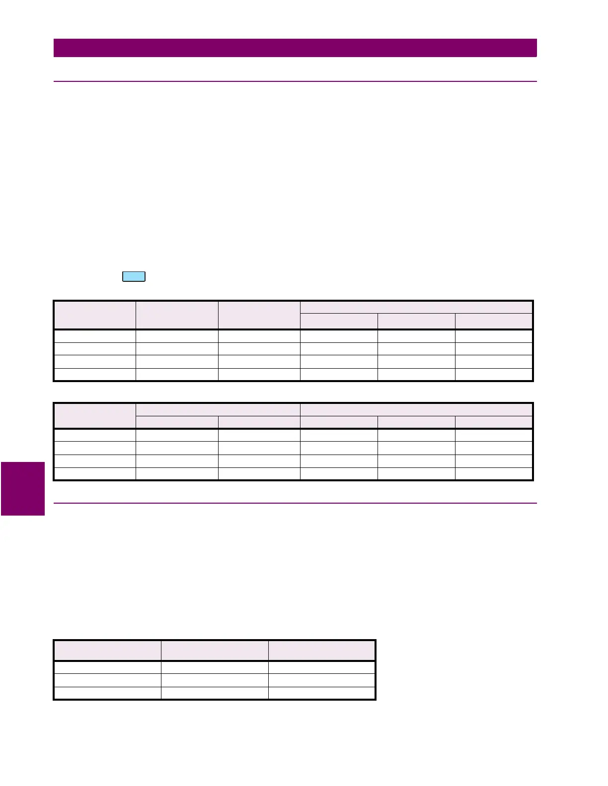
Table 7–1: NEUTRAL AND GROUND CURRENT TEST
INJECTED
CURRENT
1 A UNIT
EXPECTED
CURRENT
READING
MEASURED
GROUND
CURRENT
MEASURED NEUTRAL CURRENT
PHASE A PHASE B PHASE C
0.1 A 100 A
0.2 A 200 A
0.5 A 500 A
1 A 1000 A
Table 7–2: DIFFERENTIAL CURRENT TEST
INJECTED
CURRENT
EXPECTED CURRENT READING MEASURED DIFFERENTIAL CURRENT
DIFF. PHASE A DIFF PHASE B,C PHASE A PHASE B PHASE C
0.1 A 200 A 100 A
0.2 A 400 A 200 A
0.5 A 1000 A 500 A
1 A 2000 A 1000 A
APPLIED NEUTRAL
VOLTAGE AT 60 HZ
EXPECTED NEUTRAL
VOLTAGE
MEASURED NEUTRAL
VOLTAGE
10 V 100 V
30 V 300 V
50 V 500 V
 Loading...


