GE Power Management
489 Generator Management Relay 7-11
7 TESTING 7.3 ADDITIONAL FUNCTIONAL TESTING
7
7.3.3 REACTIVE POWER TEST
The specification for reactive power is ±1% of × 2 × CT × VT × VT
full scale
at
I
avg
< 2 × CT. Perform the steps below to
verify accuracy and trip element.
1. Alter the following system setpoints:
S2 SYSTEM SETUP\CURRENT SENSING\PHASE CT PRIMARY:
5000
S2 SYSTEM SETUP\VOLTAGE SENSING\VT CONNECTION TYPE:
Wye
S2 SYSTEM SETUP\VOLTAGE SENSING\VOLTAGE TRANSFORMER RATIO:
100:1
S2 SYSTEM SETUP\GEN. PARAMETERS\GENERATOR RATED MVA:
100
S2 SYSTEM SETUP\GEN. PARAMETERS\GENERATOR RATED POWER FACTOR:
0.85
S2 SYSTEM SETUP\GEN. PARAMETERS\GENERATOR VOLTAGE PHASE-PHASE:
12000
The rated reactive power is .
2. Alter the following reactive power setpoints:
S7 POWER ELEMENTS\REACTIVE POWER\REACTIVE POWER ALARM:
Unlatched
S7 POWER ELEMENTS\REACTIVE POWER\ASSIGN ALARM RELAYS(2-5):
---5
S7 POWER ELEMENTS\REACTIVE POWER\POSTIVE Mvar ALARM LEVEL:
0.6 x Rated
S7 POWER ELEMENTS\REACTIVE POWER\NEGATIVE Mvar ALARM LEVEL:
0.6 x Rated
S7 POWER ELEMENTS\REACTIVE POWER\REACTIVE POWER ALARM DELAY:
5 s
S7 POWER ELEMENTS\REACTIVE POWER\REACTIVE POWER ALARM EVENT:
On
S7 POWER ELEMENTS\REACTIVE POWER\REACTIVE POWER TRIP:
Unlatched
S7 POWER ELEMENTS\REACTIVE POWER\ASSIGN TRIP RELAYS(1-4):
1---
S7 POWER ELEMENTS\REACTIVE POWER\POSTIVE Mvar TRIP LEVEL:
0.75 x Rated
S7 POWER ELEMENTS\REACTIVE POWER\NEGATIVE Mvar TRIP LEVEL:
0.75 x Rated
S7 POWER ELEMENTS\REACTIVE POWER\REACTIVE POWER TRIP DELAY:
10 s
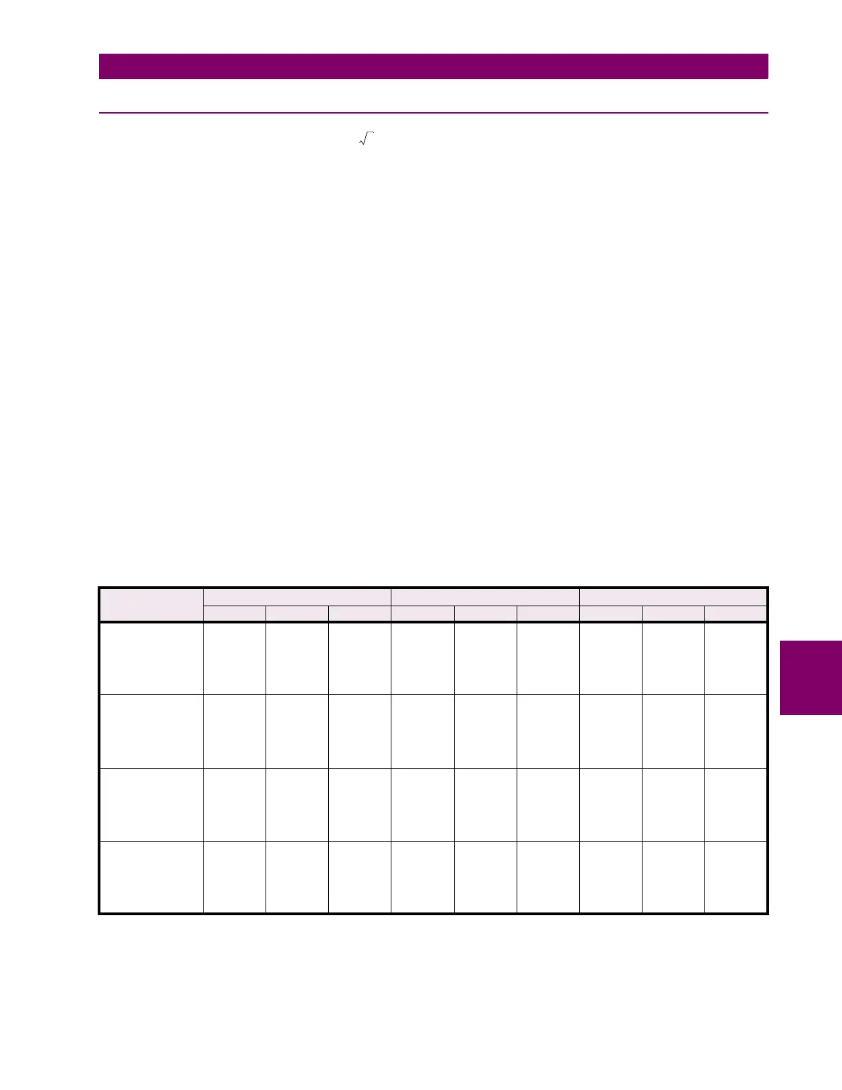
3. Inject current and apply voltage as per the table below. Verify the alarm/trip elements and the accuracy of the mea-
sured values. View the measured values in:
A2 METERING DATA\POWER METERING
4. View the Event Records in
A5 EVENT RECORD
4
Activated
8
Not Activated
CURRENT/
VOLTAGE
MVAR ALARM TRIP
EXPECTED TOLERANCE MEASURED EXPECTED OBSERVED DELAY EXPECTED OBSERVED DELAY
Vab=120V
∠
0°
Vbc=120V
∠
120°lag
Vca=120V
∠
240°lag
Ian=5 A
∠
10°lag
Ibn=5 A
∠
130°lag
Icn=5 A
∠
250°lag
18 13 to 23
8
N/A
8
N/A
Vab=120V
∠
0°
Vbc=120V
∠
120°lag
Vca=120V
∠
240°lag
Ian=5 A
∠
340°lag
Ibn=5 A
∠
100°lag
Icn=5 A
∠
220°lag
–35 –40 to –30
48
N/A
Vab=120V
∠
0°
Vbc=120V
∠
120°lag
Vca=120V
∠
240°lag
Ian=5 A
∠
330°lag
Ibn=5 A
∠
90°lag
Icn=5 A
∠
210°lag
–52 –57 to –47
44
Vab=120V
∠
0°
Vbc=120V
∠
120°lag
Vca=120V
∠
240°lag
Ian=5 A
∠
30°lag
Ibn=5 A
∠
150°lag
Icn=5 A
∠
270°lag
52 47 to 57
44
3
100 cos
1
–
0.85()()sin 52.7 Mvar±=
 Loading...


