EasyManua.ls Logo

GE 489 User Manual

GE 489
306 pages
To Next Page IconTo Next Page
To Previous Page IconTo Previous Page
Page #148 background imageLoading...
Page #148 background image
6-4 489 Generator Management Relay
GE Power Management
6.2 SUPPORTED MODBUS FUNCTIONS 6 COMMUNICATIONS
6
6.2 SUPPORTED MODBUS FUNCTIONS 6.2.1 OVERVIEW
The following functions are supported by the 489:
03 - Read Setpoints and Actual Values
04 - Read Setpoints and Actual Values
05 - Execute Operation
06 - Store Single Setpoint
07 - Read Device Status
08 - Loopback Test
16 - Store Multiple Setpoints
6.2.2 FUNCTION CODES 03/04: READ SETPOINTS/ACTUAL VALUES
Modbus implementation: Read Input and Holding Registers
489 Implementation: Read Setpoints and Actual Values
For the 489 Modbus implementation, these commands are used to read any setpoint ("holding registers") or actual value
("input registers"). Holding and input registers are 16-bit (two byte) values transmitted high order byte first. Thus all 469 set-
points and actual values are sent as two bytes. The maximum of 125 registers can be read in one transmission. Function
codes 03 and 04 are configured to read setpoints or actual values interchangeably since some PLCs do not support both
function codes.
The slave response to these function codes is the slave address, function code, a count of the number of data bytes to fol-
low, the data itself and the CRC. Each data item is sent as a two byte number with the high order byte sent first. The CRC
is sent as a two byte number with the low order byte sent first.
MESSAGE FORMAT AND EXAMPLE
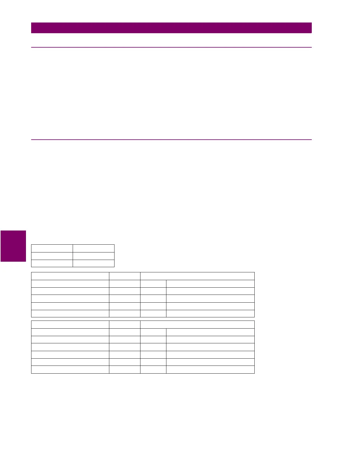
Request slave 11 to respond with 2 registers starting at address 0235. For this example, the register data in these
addresses is:
ADDRESS DATA
0235 0064
0236 000A
MASTER TRANSMISSION: BYTES EXAMPLE (HEX):
SLAVE ADDRESS 1 0B message for slave 11
FUNCTION CODE 1 03 read registers
DATA STARTING ADDRESS 2 02 35 data starting at 0235
NUMBER OF SETPOINTS 2 00 02 2 registers (4 bytes total)
CRC 2 D5 17 CRC calculated by the master
SLAVE RESPONSE: BYTES EXAMPLE (HEX):
SLAVE ADDRESS 1 0B response message from slave 11
FUNCTION CODE 1 03 read registers
BYTE COUNT 1 04 2 registers = 4 bytes
DATA 1 2 00 64 value in address 0308
DATA 2 2 00 0A value in address 0309
CRC 2 EB 91 CRC calculated by the slave

Table of Contents

Other manuals for GE 489

Question and Answer IconNeed help?

Do you have a question about the GE 489 and is the answer not in the manual?

GE 489 Specifications

General IconGeneral
BrandGE
Model489
CategoryRelays
LanguageEnglish

Summary

1 INTRODUCTION

1.1 OVERVIEW

Provides an overview of the 489 relay, its features, and general information.

1.2 SPECIFICATIONS

Details technical specifications for the 489 relay, including power supply, inputs, and outputs.

3 OPERATION

3.2 SETPOINT ENTRY

Outlines the procedure for accessing and modifying setpoints via the front panel keypad.

4 SETPOINT PROGRAMMING

6 COMMUNICATIONS

6.1 ELECTRICAL INTERFACE

Details the hardware and electrical interface, including RS485 and RS232 ports and Modbus protocol.

6.3 MEMORY MAP

Provides information on the memory map structure, including register addresses and data formats.

7 TESTING

7.1 TEST SETUP

Outlines the purpose of testing and lists the various tests to be performed on the 489 relay.

8 489PC SOFTWARE

8.1 INSTALLATION/UPGRADE

Provides information on installing, upgrading, and configuring the 489PC software and relay firmware.

APPENDIX A A.1 COMMISSIONING

A.1.1 SETPOINTS SUMMARY

Summarizes default and user-defined setpoints for the 489 relay across various pages.

Table A–1: SETPOINTS PAGE 1 – 489 SETUP

Lists default and user values for 489 SETUP setpoints, including Passcode and Serial Ports.

Table A–3: SETPOINTS PAGE 3 – DIGITAL INPUTS (Sheet 1 of 3)

Lists digital input setpoints for General Inputs A, B, C, and D, including their configurations.

Table A–5: SETPOINTS PAGE 5 – CURRENT ELEMENTS (Sheet 1 of 7)

Lists current element setpoints, covering Overcurrent Alarm, Offline Overcurrent, and Inadvertent Energization.

Table A–6: SETPOINTS PAGE 6 – VOLTAGE ELEMENTS (Sheet 1 of 3)

Lists voltage element setpoints including Undervoltage, Overvoltage, Volts/Hertz, and Underfrequency.

Table A–10: SETPOINTS PAGE 9 – THERMAL MODEL (Sheet 1 of 2)

Lists thermal model setpoints for setup, overload curves, and RTD bias parameters.

APPENDIX B B.1 STATOR GROUND FAULT PROTECTION

B.1.1 DESCRIPTION

Provides general concepts and guidelines for protecting generator stators against ground faults.

B.1.2 NEUTRAL OVERVOLTAGE ELEMENT

Describes the neutral overvoltage element for detecting stator ground faults.

B.1.3 GROUND OVERCURRENT ELEMENT

Details the ground overcurrent element as a replacement or backup for neutral overvoltage.

B.1.4 GROUND DIRECTIONAL ELEMENT

Explains the ground directional element using Vneutral and ground current inputs for fault detection.

B.1.5 THIRD HARMONIC VOLTAGE ELEMENT

Covers the third harmonic voltage element for detecting stator ground faults near the generator neutral.

Related product manuals