7-8 489 Generator Management Relay
GE Power Management
7.2 HARDWARE FUNCTIONAL TESTING 7 TESTING
7
b) 0-1mA
1. Alter the following setpoints:
S11 ANALOG I/O\ANALOG INPUT1\ANALOG INPUT1:
0-1 mA
S11 ANALOG I/O\ANALOG INPUT1\ANALOG INPUT1 MINIMUM:
0
S11 ANALOG I/O\ANALOG INPUT1\ANALOG INPUT1 MAXIMUM:
1000 (repeat for analog inputs 2 to 4)
2. Analog output values should be ±0.01 mA on the ammeter. Measured analog input values should be ±10 units. Force
the analog outputs using the following setpoints:
S12 TESTING\TEST ANALOG OUTPUT\FORCE ANALOG OUTPUTS FUNCTION:
Enabled
S12 TESTING\TEST ANALOG OUTPUT\ANALOG OUTPUT 1 FORCED VALUE:
0% (enter %, repeat for outputs 2 to 4)
Verify the ammeter readings as well as the measured analog input readings. View the measured values in:
A2 METERING DATA\ANALOG INPUTS
7.2.9 OUTPUT RELAYS
To verify the functionality of the output relays, perform the following steps:
1. Using the setpoint:
S12 TESTING\TEST OUTPUT RELAYS\FORCE OPERATION OF RELAYS:
R1 TRIP
select and store values as per the table below, verifying operation
R6 Service relay is failsafe or energized normally, operating R6 causes it to de-energize.
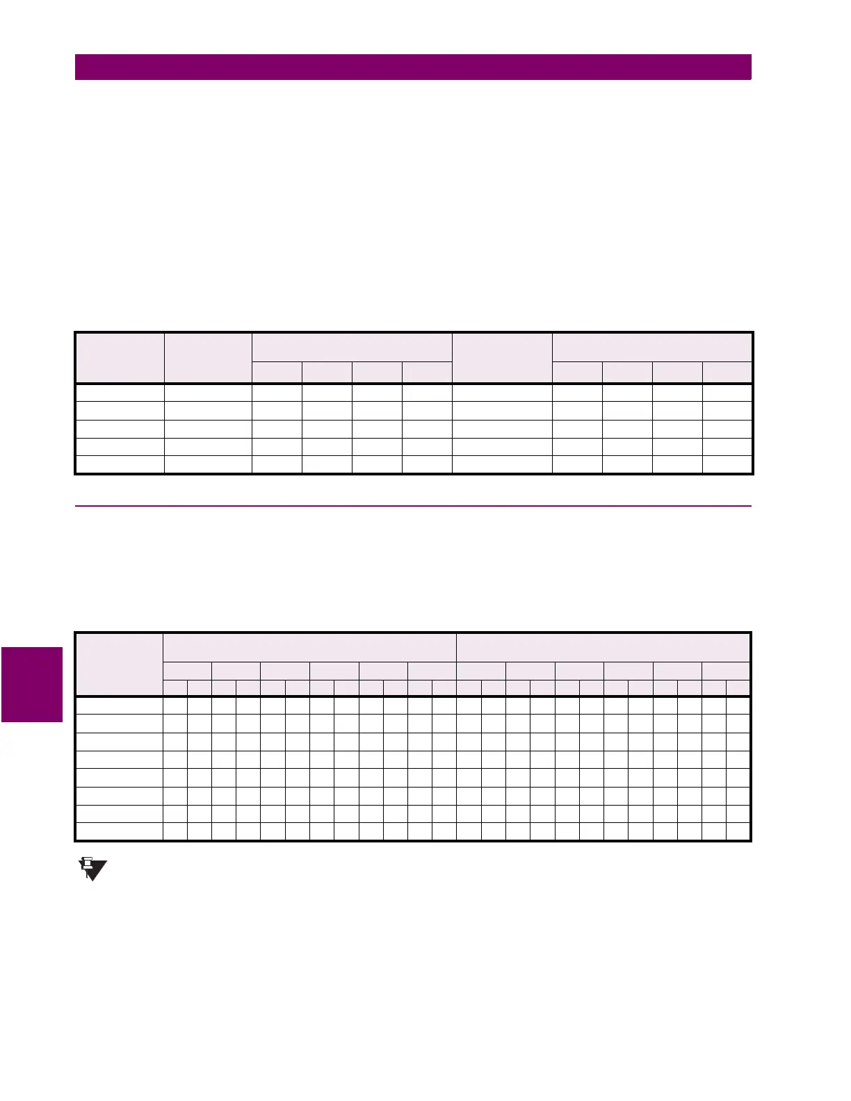
Table 7–4: ANALOG INPUT/OUTPUT TEST, 0 to 1 mA INPUT
ANALOG
OUTPUT
FORCE
VALUE
EXPECTED
AMMETER
READING
MEASURED AMMETER READING
(MA)
EXPECTED
ANALOG INPUT
READING
MEASURED ANALOG INPUT
READING (UNITS)
1 2 3 4 1 2 3 4
0% 0 mA 0 units
25% 0.25 mA 250 units
50% 0.50 mA 500 units
75% 0.75 mA 750 units
100% 1.00 mA 1000 units
Table 7–5: OUTPUT RELAYS
FORCE
OPERATION
SETPOINT
EXPECTED MEASUREMENT
(
4
FOR SHORT)
ACTUAL MEASUREMENT
(
4
FOR SHORT)
R1 R2 R3 R4 R5 R6 R1 R2 R3 R4 R5 R6
NO NC NO NC NO NC NO NC NO NC NO NC NO NC NO NC NO NC NO NC NO NC NO NC
R1 Trip
444444
R2 Auxiliary
44 4 4 44
R3 Auxiliary
444 444
R4 Auxiliary
4444 44
R5 Alarm
444444
R6 Service
444444
All Relays
44444 4
No Relays
444444
NOTE
 Loading...


