GE Power Management
489 Generator Management Relay 7-15
7 TESTING 7.3 ADDITIONAL FUNCTIONAL TESTING
7
Apply the values shown in the table below and verify the accuracy and the operation of phase differential element.
View the measured values in:
A2:METERING DATA\CURRENT METERING
or press the button when the trip element is activated.
As in Figure 7–2: SECONDARY INJECTION SETUP #2 on page 7–12,
I
A
(test set) =
I
A
and
I
B
(test set) =
I
a
3. Repeat for phases B & C. Rewiring of Figure 7–2: SECONDARY INJECTION SETUP #2 on page 7–12 is required.
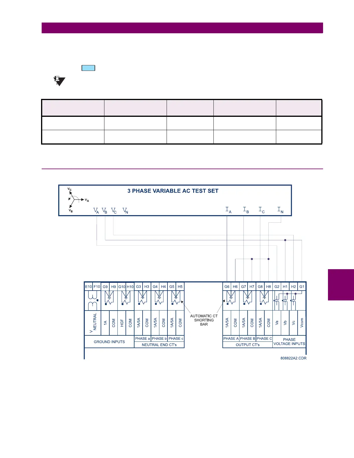
7.3.9 INJECTION TEST SETUP #3
Figure 7–4: SECONDARY INJECTION TEST SETUP #3
APPLIED CURRENT AS
SHOWN ON 489
EXPECTED RESULT EXPECTED
DIFFERENTIAL
CURRENT
OBSERVED RESULT MEASURED
DIFFERENTIAL
CURRENT
I
A
= 1000 A
∠
0
°
I
a
= 1000 A
∠
180
°
lag
NO TRIP 0 A
I
A
= 1000 A
∠
0
°
I
a
= 940 A
∠
190
°
lag
PHASE DIFFERENTIAL
TRIP
179 A
NOTE
 Loading...


