4-2 489 Generator Management Relay
GE Power Management
4.1 OVERVIEW 4 SETPOINT PROGRAMMING
4
4.1.3 DUAL SETPOINTS
The 489 has dual settings for the current, voltage, power, RTD, and thermal model protection elements (S5 to S9). These
setpoints are organized in two groups: the main group (Group 1) and the alternate group (Group 2). Only one group of set-
tings is active in the protection scheme at a time. The active group can be selected using the
ACTIVATE SETPOINT GROUP
setpoint or an assigned digital input in S3 Digital Inputs. The LED indicator on the faceplate of the 489 will indicate when
the alternate setpoints are active in the protection scheme. Independently, the setpoints in either group can be viewed and/
or edited using the
EDIT SETPOINT GROUP
setpoint. Headers for each setpoint message subgroup that has dual settings will
be denoted by a superscript number indicating which setpoint group is being viewed or edited. Also, when a setpoint that
has dual settings is stored, the flash message that appears will indicate which setpoint group setting has been changed.
If only one setting group is required, edit and activate only Group 1 (that is, do not assign a digital input to Dual Setpoints,
and do not alter the
ACTIVATE SETPOINT GROUP
setpoint or
EDIT SETPOINT GROUP
setpoint in
S3 DIGITAL INPUTS
).
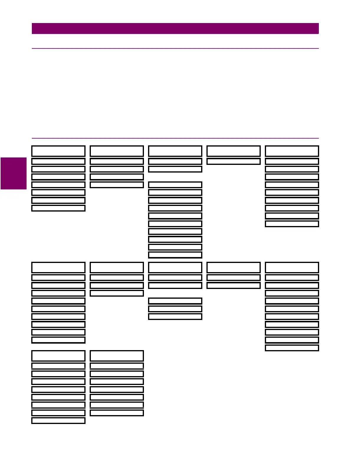
4.1.4 SETPOINT MESSAGE MAP
yy
S1 SETPOINTS
yy
489 SETUP
yy
S2 SETPOINTS
yy
SYSTEM SETUP
yy
S3 SETPOINTS
yy
DIGITAL INPUTS
yy
S4 SETPOINTS
yy
OUTPUT RELAYS
yy
S5 SETPOINTS
yy
CURRENT ELEMENTS
y
PASSCODE
y
CURRENT SENSING
y
BREAKER STATUS
y
RELAY RESET MODE
y
OVERCURRENT ALARM
y
PREFERENCES
y
VOLTAGE SENSING
y
GENERAL INPUT A
y
OFFLINE O/C
y
SERIAL PORT
y
GEN. PARAMETERS ↓
y
INADVERTENT ENERG
y
REAL TIME CLOCK
y
SERIAL START/STOP
y
GENERAL INPUT G
y
PHASE OVERCURRENT
y
DEFAULT MESSAGES
y
REMOTE RESET
y
NEGATIVE SEQUENCE
y
MESSAGE SCRATCHPAD
y
TEST INPUT
y
GROUND O/C
y
CLEAR DATA
y
THERMAL RESET
y
PHASE DIFFERENTIAL
y
DUAL SETPOINTS
y
GROUND DIFFERENTIAL
y
SEQUENTIAL TRIP
y
HIGH-SET PHASE O/C
y
FIELD-BKR DISCREP.
y
TACHOMETER
y
WAVEFORM CAPTURE
y
GND SWITCH STATUS
yy
S6 SETPOINTS
yy
VOLTAGE ELEMENTS
yy
S7 SETPOINTS
yy
POWER ELEMENTS
yy
S8 SETPOINTS
yy
RTD TEMPERATURE
yy
S9 SETPOINTS
yy
THERMAL MODEL
yy
S10 SETPOINTS
yy
MONITORING
y
UNDERVOLTAGE
y
REACTIVE POWER
y
RTD TYPES
y
MODEL SETUP
y
TRIP COUNTER
y
OVERVOLTAGE
y
REVERSE POWER
y
RTD #1
y
THERMAL ELEMENTS
y
BREAKER FAILURE
y
VOLTS/HERTZ
y
LOW FORWARD POWER
↓
y
TRIP COIL MONITOR
y
PHASE REVERSAL
y
RTD #12
y
VT FUSE FAILURE
y
UNDERFREQUENCY
y
OPEN RTD SENSOR
y
CURRENT DEMAND
y
NEUTRAL O/V (Fund)
y
RTD SHORT/LOW TEMP
y
MW DEMAND
y
NEUTRAL O/V (3rd)
y
Mvar DEMAND
y
LOSS OF EXCITATION
y
MVA DEMAND
y
DISTANCE ELEMENT
y
PULSE OUTPUT
y
RUNNING HOUR SETUP
yy
S11 SETPOINTS
yy
ANALOG I/O
yy
S12 SETPOINTS
yy
489 TESTING
y
ANALOG OUTPUT 1
y
SIMULATION MODE
y
ANALOG OUTPUT 2
y
PRE-FAULT SETUP
y
ANALOG OUTPUT 3
y
FAULT SETUP
y
ANALOG OUTPUT 4
y
TEST OUTPUT RELAYS
y
ANALOG INPUT 1
y
TEST ANALOG OUTPUT
y
ANALOG INPUT 2
y
COMM PORT MONITOR
y
ANALOG INPUT 3
y
FACTORY SERVICE
y
ANALOG INPUT 4
 Loading...


