GE Power Management
489 Generator Management Relay 4-35
4 SETPOINT PROGRAMMING 4.7 S6 VOLTAGE ELEMENTS
4
4.7.7 NEUTRAL OVERVOLTAGE (FUNDAMENTAL)
The neutral overvoltage function responds to fundamental frequency voltage at the generator neutral. It provides ground
fault protection for approximately 95% of the stator windings. 100% protection is provided when this element is used in con-
junction with the Neutral Undervoltage (3rd harmonic) function. The alarm element is definite time and the trip element can
be either definite time or an inverse time curve. When the neutral voltage rises above the pickup level the element will begin
to time out. If the time expires an alarm or trip will occur. The reset rate is a linear reset time from the threshold of trip. The
alarm and trip levels are programmable in terms of Neutral VT secondary voltage.
NEUTRAL O/V (FUND)
[ENTER] for more
SUPERVISE WITH
DIGITAL INPUT: No
Range: Yes, No. Seen only if a digital input assigned to
GROUND SWITCH STATUS
NEUTRAL OVERVOLTAGE
ALARM: Off
Range: Off, Latched, Unlatched
ASSIGN ALARM
RELAYS (2-5): ---5
Range: Any combination of Relays 2 to 5
NEUTRAL O/V ALARM
LEVEL: 3.0 Vsec
Range: 2.0 to 100.0 Vsec in steps of 0.1
NEUTRAL OVERVOLTAGE
ALARM DELAY: 1.0 s
Range: 0.1 to 120.0 s in steps of 0.1
NEUTRAL OVERVOLTAGE
ALARM EVENTS: Off
Range: On, Off
NEUTRAL OVERVOLTAGE
TRIP: Off
Range: Off, Latched, Unlatched
ASSIGN TRIP
RELAYS (1-4): 1---
Range: Any combination of Relays 1 to 4
NEUTRAL O/V TRIP
LEVEL: 5.0 Vsec
Range: 2.0 to 100.0 Vsec in steps of 0.1
NEUTRAL OVERVOLTAGE
TRIP DELAY: 1.0 s
Range: 0.1 to 120.0 s in steps of 0.1
NEUTRAL O/V CURVE
RESET RATE: 0.0
Range: 0.0 to 999.9 in steps of 0.1
NEUTRAL O/V TRIP
ELEMENT: Definite Time
Range: Curve, Definite Time
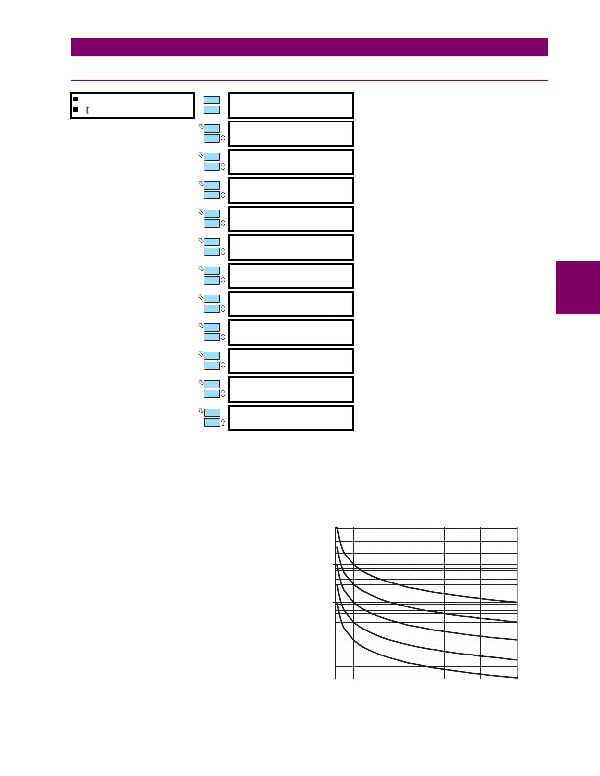
The formula for the curve is:
where
T
= trip time in seconds
D
=
NEUTRAL OVERVOLTAGE TRIP DELAY
setpoint
V
= neutral voltage
V
pickup
=
NEUTRAL O/V TRIP LEVEL
setpoint
The neutral overvoltage curves are shown on the right.
Refer to Appendix B for Application Notes.
MESSAGE
ESCAPE
MESSAGE
ESCAPE
MESSAGE
ESCAPE
MESSAGE
ESCAPE
MESSAGE
ESCAPE
MESSAGE
ESCAPE
MESSAGE
ESCAPE
MESSAGE
ESCAPE
MESSAGE
ESCAPE
MESSAGE
ESCAPE
MESSAGE
ESCAPE
T
D
VV
pickup
⁄()1–
-----------------------------------------= when
VV
pickup
>
0.1
1
10
100
1000
1 1.1 1.2 1.3 1.4 1.5 1.6 1.7 1.8 1.9 2
Multiples of Overvoltage Pickup
10
3
1
0.3
0.1
Time to Trip (seconds)
TIME DELAY SETTING
 Loading...


