GE Power Management
489 Generator Management Relay 4-51
4 SETPOINT PROGRAMMING 4.10 S9 THERMAL MODEL
4
4.10 S9 THERMAL MODEL 4.10.1 489 THERMAL MODEL
The thermal model of the 489 is primarily intended for induction generators, especially those that start on the system bus in
the same manner as induction motors. However, some of the thermal model features may be used to model the heating
that occurs in synchronous generators during overload conditions.
One of the principle enemies of generator life is heat. Generator thermal limits are dictated by the design of both the stator
and the rotor. Induction generators that start on the system bus have three modes of operation: locked rotor or stall (when
the rotor is not turning), acceleration (when the rotor is coming up to speed), and generating (when the rotor turns at super-
synchronous speed). Heating occurs in the generator during each of these conditions in very distinct ways. Typically, during
the generator starting, locked rotor and acceleration conditions, the generator will be rotor limited. That is to say that the
rotor will approach its thermal limit before the stator. Under locked rotor conditions, voltage is induced in the rotor at line fre-
quency, 50 or 60 Hz. This voltage causes a current to flow in the rotor, also at line frequency, and the heat generated (
I
2
R
)
is a function of the effective rotor resistance. At 50 or 60 Hz, the reactance of the rotor cage causes the current to flow at
the outer edges of the rotor bars. The effective resistance of the rotor is therefore at a maximum during a locked rotor con-
dition as is rotor heating. When the generator is running at above rated speed, the voltage induced in the rotor is at a low
frequency (approximately 1 Hz) and therefore, the effective resistance of the rotor is reduced quite dramatically. During
overloads, the generator thermal limit is typically dictated by stator parameters. Some special generators might be all stator
or all rotor limited. During acceleration, the dynamic nature of the generator slip dictates that rotor impedance is also
dynamic, and a third thermal limit characteristic is necessary.
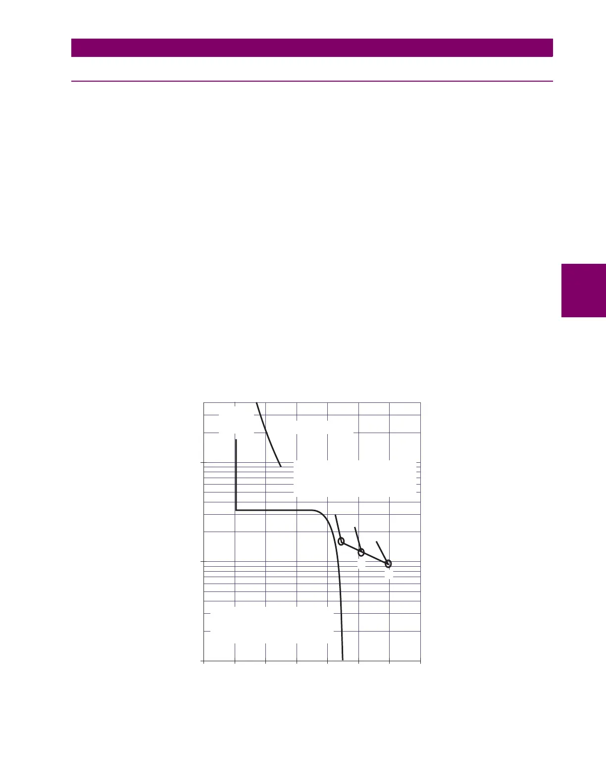
The figure below illustrates typical thermal limit curves for induction motors. The starting characteristic is shown for a high
inertia load at 80% voltage. If the machine started quicker, the distinct characteristics of the thermal limit curves would not
be required and the running overload curve would be joined with locked rotor safe stall times to produce a single overload
curve.
The generator manufacturer should provide a safe stall time or thermal limit curves for any generator that is started as an
induction motor. These thermal limits are intended to be used as guidelines and their definition is not always precise. When
operation of the generator exceeds the thermal limit, the generator insulation does not immediately melt, rather, the rate of
insulation degradation reaches a point where continued operation will significantly reduce generator life.
Figure 4–10: TYPICAL TIME-CURRENT AND THERMAL LIMIT CURVES (ANSI/IEEE C37.96)
1
10
8
6
4
2
100
80
60
40
20
200
300
400
0 100 200 300 400 500 600 % CURRENT
TIME-SECONDS
HIGH
INERTIA
MOTOR
RUNNING OVERLOAD
A
G
B
C
A,B,AND C ARE THE
ACCELERATION THERMAL LIMIT
CURVES AT 100%, 90%, AND
80%VOLTAGE, REPECTIVELY
E,F, AND G ARE THE
SAFE STALL THERMAL LIMIT
TIMES AT 100%, 90%, AND
80%VOLTAGE, REPECTIVELY
E
F
806827A1.CDR
 Loading...


