4-12 489 Generator Management Relay
GE Power Management
4.4 S3 DIGITAL INPUTS 4 SETPOINT PROGRAMMING
4
4.4.5 REMOTE RESET
Once an input is assigned to the Remote Reset function, shorting that input will reset any latched trips or alarms that may
be active, provided that any thermal lockout time has expired and the condition that caused the alarm or trip is no longer
present.
If an input is assigned to the tachometer function, it may not be used here.
4.4.6 TEST INPUT
Once the 489 is in service, it may be tested from time to time as part of a regular maintenance schedule. The unit will have
accumulated statistical information relating historically to generator and breaker operation. This information includes: last
trip data, peak demand data, MWh and Mvarh metering, parameter averages, RTD maximums, analog input minimums and
maximums, number of trips, number of trips by type, number of breaker operations, the number of thermal resets, total gen-
erator running hours, and the event record. When the unit is under test and one of the inputs is assigned to the Test Input
function, shorting that input will prevent all of this data from being corrupted or updated.
If an input is assigned to the tachometer function, it may not be used here.
4.4.7 THERMAL RESET
During testing or in an emergency, it may be desirable to reset the thermal memory used to zero. If an input is assigned to
the Thermal Reset function, shorting that input will reset the thermal memory used to zero. All Thermal Resets will be
recorded as events.
If an input is assigned to the tachometer function, it may not be used here.
4.4.8 DUAL SETPOINTS
If an input is assigned to the tachometer function, it may not be used here.
This feature allows for dual settings for the current, voltage, power, RTD, and thermal model protection elements (setpoint
pages S5 to S9). These settings are organized in two setpoint groups: the main group (Group 1) and the alternate group
(Group 2). Only one group of settings are active in the protection scheme at a time.
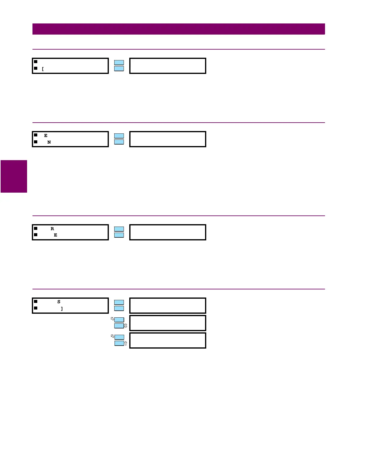
REMOTE RESET
[ENTER] for more
ASSIGN DIGITAL
INPUT: None
Range: None, Input 1, Input 2, Input 3, Input 4, Input 5,
Input 6, Input 7
TEST INPUT
[ENTER] for more
ASSIGN DIGITAL
INPUT: None
Range: None, Input 1, Input 2, Input 3, Input 4, Input 5,
Input 6, Input 7
THERMAL RESET
[ENTER] for more
ASSIGN DIGITAL
INPUT: None
Range: None, Input 1, Input 2, Input 3, Input 4, Input 5,
Input 6, Input 7
DUAL SETPOINTS
[ENTER] for more
ASSIGN DIGITAL
INPUT: None
Range: None, Input 1, Input 2, Input 3, Input 4, Input 5,
Input 6, Input 7
ACTIVATE SETPOINT
GROUP: Group 1
Range: Group 1, Group 2
EDIT SETPOINT
GROUP: Group 1
Range: Group 1, Group 2
MESSAGE
ESCAPE
MESSAGE
ESCAPE
 Loading...


