GE Power Management
489 Generator Management Relay 2-15
2 INSTALLATION 2.2 ELECTRICAL
2
2.2.14 DIELECTRIC STRENGTH TESTING
It may be required to test for dielectric strength (“flash” or hi-pot”) with the 489 installed. The 489 is rated for 2000 V DC iso-
lation between relay contacts, CT inputs, VT inputs, trip coil supervision, and the safety ground terminal G12. Some pre-
cautions are required to prevent 489 damage during these tests.
Filter networks and transient protection clamps are used between control power, trip coil supervision, and the filter ground
terminal G11. This filtering is intended to filter out high voltage transients, radio frequency interference (RFI), and electro-
magnetic interference (EMI). The filter capacitors and transient suppressors could be damaged by application continuous
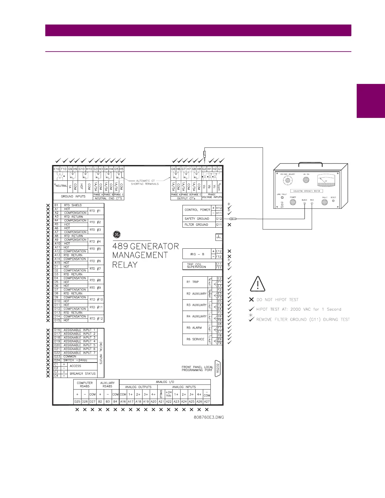
high voltage. Disconnect filter ground terminal G11 during testing of control power and trip coil supervision. CT inputs, VT
inputs, and output relays do not require any special precautions. Low voltage inputs (<30 V), RTDs, analog inputs, analog
outputs, digital inputs, and RS485 communication ports are not to be tested for dielectric strength under any circumstance
(see below).
Figure 2–17: TESTING THE 489 FOR DIELECTRIC STRENGTH
GE Power Management
 Loading...


