GE Power Management
489 Generator Management Relay B-3
APPENDIX B B.1 STATOR GROUND FAULT PROTECTION
B
B.1.3 GROUND OVERCURRENT ELEMENT
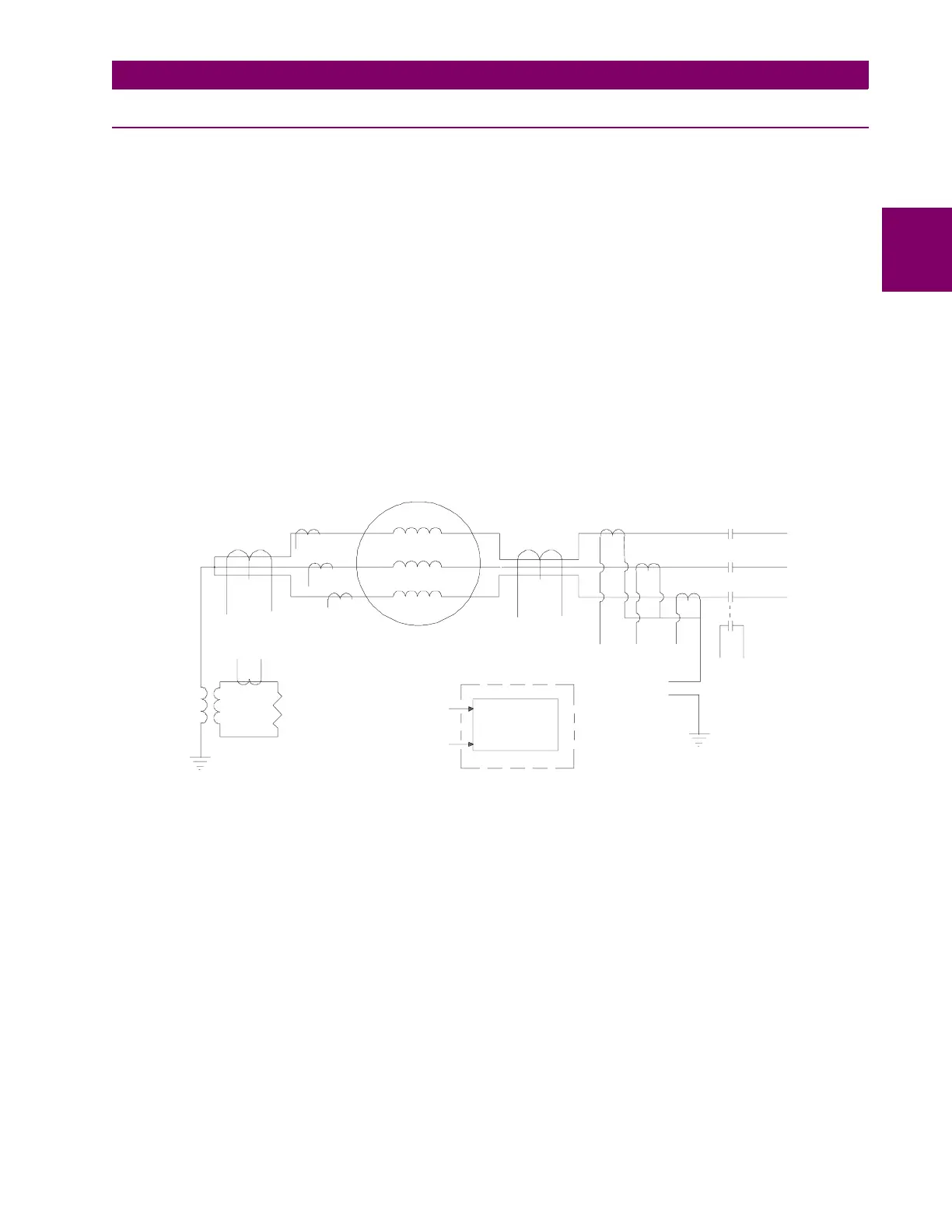
The ground overcurrent element can be used as a direct replacement or a backup for the neutral overvoltage element, with
the appropriate current signal from the generator neutral point, for grounded generators. This element can also be used
with a core balance CT, either in the neutral end or the output end of the generator, as shown below. The use of the special
CT, with its dedicated input to the relay, offers very sensitive current detection, but still does not offer protection for the full
stator. The setting of this element must be above the maximum unbalance current that normally flows in the neutral circuit.
Having the element respond only to the fundamental frequency component allows an increase in sensitivity.
The core balance CT can be a conventional CT or a 50:0.025 ground CT, allowing the measurement of primary-side current
levels down to 0.25 A. Using a core balance CT, on the output side of the transformer will provide protection against stator
ground faults in ungrounded generators, provided that there is a source of zero-sequence current from the grid.
Though in theory one could use this element with a zero sequence current signal obtained from a summation of the three
phase currents (neutral end or output end), by connecting it in the star point of the phase CTs, options 4 and 5 in the figure
below, this approach is not very useful. The main drawback, for impedance-grounded generators is that the zero-sequence
current produced by the CT ratio and phase errors could be much larger than the zero sequence current produced by a real
ground fault inside the generator.
Again the time delay on this element must be coordinated with protection elements downstream, if the generator is
grounded. Refer to the relay manual/3/ for the range of settings of the pickup levels and the time delays. The time delay on
this element should always be longer than the longest delay on line protection downstream.
Figure B–3: GROUND OVERCURRENT ELEMENT WITH DIFFERENT CURRENT SOURCE SIGNALS
GNDCUR1R2.CDR
489
GENERATOR
CORE
BALANCE
CT
CORE
BALANCE
CT
Phase CTs
BREAKER
Breaker
Aux.
Option 2
Option 1
Option 5
(similar to
Option 4)
Option 3
Option 4
Ground
Overcurrent
Element
Ground current input
from one of the five
options
 Loading...


