7-14 489 Generator Management Relay
GE Power Management
7.3 ADDITIONAL FUNCTIONAL TESTING 7 TESTING
7
7.3.8 PHASE DIFFERENTIAL TRIP TEST
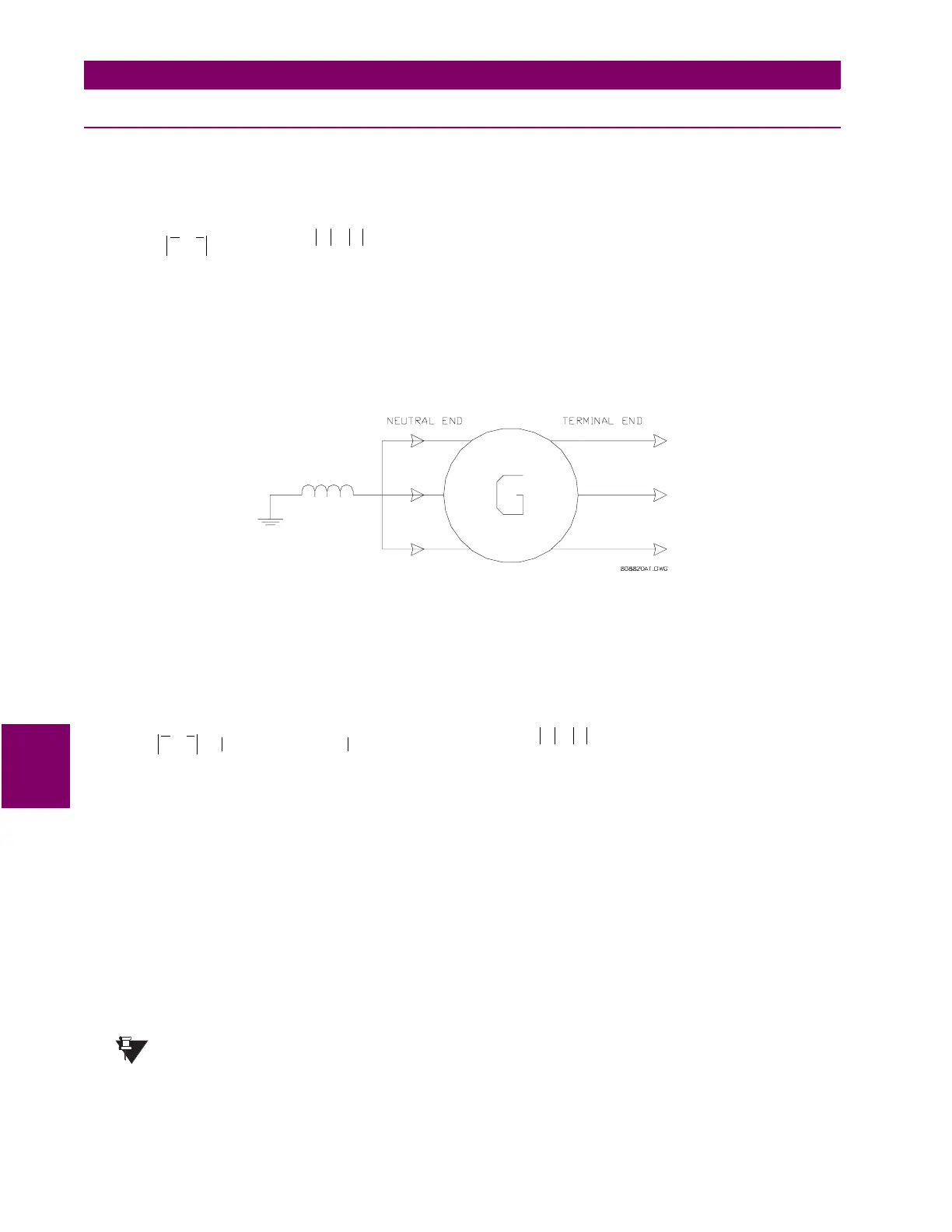
The 489 phase differential compares the current level at terminal end with the current level at neutral end. The differential
element will trip when:
given and
where:
I
diff
= differential current
I
restraint
= restraint current
k
= differential element characteristic slope in percent
(use
DIFFERENTIAL TRIP SLOPE1
if
I
restraint
< 2 × CT,
DIFFERENTIAL TRIP SLOPE2
if
I
restraint
≥ 2 × CT)
I
A
= phase current measured at the output CT
I
a
= phase current measured at the neutral end CT
See Section 4.6.8: PHASE DIFFERENTIAL on page 4–26 for additional details.
Figure 7–3: PHASE DIFFERENTIAL
The following is a sample calculation of a trip scenario. Given the following settings and values,
DIFFERENTIAL TRIP SLOPE1:
10% (user setting)
DIFFERENTIAL TRIP SLOPE2:
20% (user setting)
I
A
= 1.5 × CT at 0°,
I
a
= 1.47 × CT at 190° lag
The calculations are as follows:
and
Since
I
restraint
< 2 × CT, the differential trip slope
k
= 0.1 or 10% and .
Therefore, since
I
diff
>
I
trip
, the differential TRIP will operate.
The 489 specification for differential phase timing accuracy is ±0.5% of total time. Pickup accuracy is per the output current
inputs (±0.5% of 2 × CT when the injected current is less than 2 × CT and ±1% of 20 × CT when the injected current is equal
to or greater than 2 × CT). Perform the steps below to verify accuracy for phase A.
1. Alter the following setpoints:
S2 SYSTEM SETUP\CURRENT SENSING\PHASE CT PRIMARY:
1000A
S5 CURRENT ELEMENT\PHASE DIFFERENTIAL\PHASE DIFFERENTIAL TRIP:
Unlatched
S5 CURRENT ELEMENT\PHASE DIFFERENTIAL\DIFFERENTIAL TRIP MIN. PICKUP:
0.10xCT
S5 CURRENT ELEMENT\PHASE DIFFERENTIAL\DIFFERENTIAL TRIP SLOPE1:
10%
S5 CURRENT ELEMENT\PHASE DIFFERENTIAL\DIFFERENTIAL TRIP SLOPE2:
20%
2. Measured values should be ±5.0 A.
There could be further error due to uncertainty in the phase measurement. It is recommended that the phase
be measured from 489 instead of the current source for the purposes of this test.
I
diff
kI
restraint
×>
I
diff
I
A
I
a
–=
I
restraint
I
A
I
a
+
2
---------------------=
I
diff
I
A
I
a
– 1.5 1.448–
j
0.255+ 0.26 CT×== =
I
restraint
I
A
I
a
+
2
--------------------- 1.485 CT×==
I
trip
kI
restraint
× 0.1 1.485× 0.1485 CT×===
NOTE
 Loading...


