GE Power Management
489 Generator Management Relay 7-9
7 TESTING 7.3 ADDITIONAL FUNCTIONAL TESTING
7
7.3 ADDITIONAL FUNCTIONAL TESTING 7.3.1 OVERLOAD CURVE TEST
The specification for overload curve timing accuracy is ±100 ms or ±2% of time to trip. Pickup accuracy is as per the current
inputs (±0.5% of 2 × CT when the injected current is less than 2 × CT and ±1% of 20 × CT when the injected current is equal
to or greater than 2 × CT). Perform the steps below to verify accuracy.
1. Alter the following setpoints:
S2 SYSTEM SETUP\GEN. PARAMETERS\GENERATOR RATED:
1.04
S2 SYSTEM SETUP\GEN. PARAMETERS\GENERATOR VOLTAGE PHASE-PHASE:
600
(Note: This is equivalent to setting FLA = 1000 A – For testing purposes ONLY!)
S2 SYSTEM SETUP\CURRENT SENSING\PHASE CT PRIMARY:
1000
S9 THERMAL MODEL\MODEL SETUP\SELECT CURVE STYLE:
Standard
S9 THERMAL MODEL\MODEL SETUP\OVERLOAD PICKUP LEVEL:
1.10xFLA
S9 THERMAL MODEL\MODEL SETUP\UNBALANCE BIAS K FACTOR:
0
S9 THERMAL MODEL\MODEL SETUP\HOT/COLD SAFE STALL RATIO:
1.00
S9 THERMAL MODEL\MODEL SETUP\ENABLE RTD BIASING:
No
S9 THERMAL MODEL\MODEL SETUP\STANDARD OVERLOAD CURVE NUMBER:
4
S9 THERMAL MODEL\MODEL SETUP\ENABLE THERMAL MODEL:
Yes
S9 THERMAL MODEL\THERMAL ELEMENTS\THERMAL MODEL TRIP:
Latched or Unlatched
2. Any trip must be reset prior to each test. Short the emergency restart terminals momentarily immediately prior to each
overload curve test to ensure that the thermal capacity used is zero. Failure to do so will result in shorter trip times.
Inject the current of the proper amplitude to obtain the values as shown and verify the trip times. Motor load may be
viewed in:
A2 METERING DATA\CURRENT METERING
3. Thermal capacity used and estimated time to trip may be viewed in:
A1 STATUS\GENERATOR STATUS
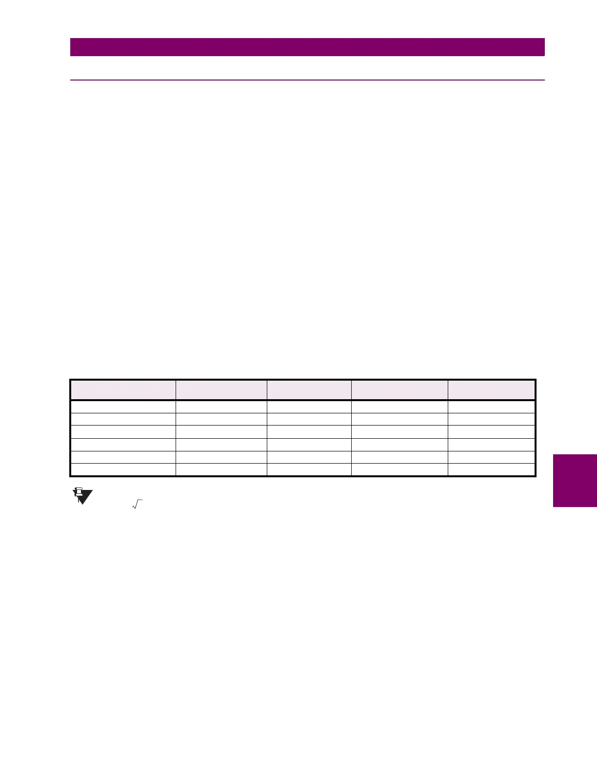
AVERAGE PHASE
CURRENT DISPLAYED
PICKUP LEVEL EXPECTED TIME TO
TRIP
TOLERANCE RANGE MEASURED TIME TO
TRIP (SEC.)
1050 A 1.05
×
FLA never n/a
1200 A 1.20
×
FLA 795.44 sec. 779.53 to 811.35 sec.
1750 A 1.75
×
FLA 169.66 sec. 166.27 to 173.05 sec.
3000 A 3.00
×
FLA 43.73 sec. 42.86 to 44.60 sec.
6000 A 6.00
×
FLA 9.99 sec. 9.79 to 10.19 sec.
10000 A 10.00
×
FLA 5.55 sec. 5.44 to 5.66 sec.
NOTE
FLA
Generator Rated MVA
3 Generator Phase-to-Phase Voltage×
-----------------------------------------------------------------------------------------------------------=
 Loading...


