7-10 489 Generator Management Relay
GE Power Management
7.3 ADDITIONAL FUNCTIONAL TESTING 7 TESTING
7
7.3.2 POWER MEASUREMENT TEST
The specification for reactive and apparent power is ± 1% of × 2 × CT × VT × VT
full-scale
at
I
avg
< 2 × CT. Perform the
steps below to verify accuracy.
1. Alter the following setpoints:
S2 SYSTEM SETUP\CURRENT SENSING\PHASE CT PRIMARY:
1000
S2 SYSTEM SETUP\VOLTAGE SENSING\VT CONNECTION TYPE:
Wye
S2 SYSTEM SETUP\VOLTAGE SENSING\VOLTAGE TRANSFORMER RATIO:
10.00:1
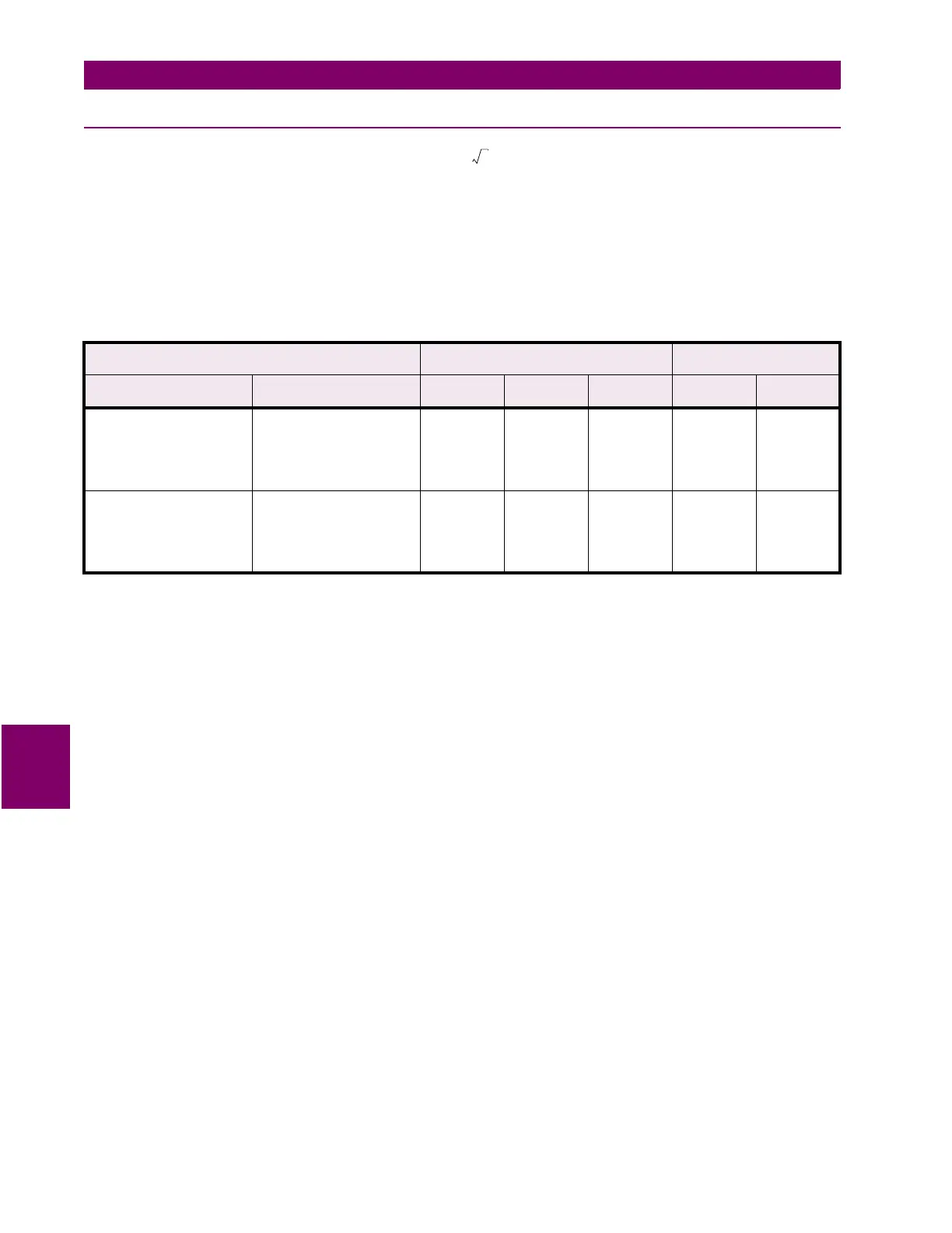
2. Inject current and apply voltage as per the table below. Verify accuracy of the measured values. View the measured
values in:
A2 METERING DATA\POWER METERING
INJECTED CURRENT / APPLIED VOLTAGE (IA IS THE
REFERENCE VECTOR)
POWER QUANTITY POWER FACTOR
1 A UNIT 5 A UNIT EXPECTED TOLERANC
E
MEASURED EXPECTED MEASURED
Ia = 1 A
∠
0
°
Ib = 1 A
∠
120
°
lag
Ic = 1 A
∠
240
°
lag
Va = 120 V
∠
342
°
lag
Vb = 120 V
∠
102
°
lag
Vc = 120 V
∠
222
°
lag
Ia = 5 A
∠
0
°
Ib = 5 A
∠
120
°
lag
Ic = 5 A
∠
240
°
lag
Va = 120 V
∠
342
°
lag
Vb = 120 V
∠
102
°
lag
Vc = 120 V
∠
222
°
lag
+3424 kW
3329 to
3519 kW
0.95 lag
Ia = 1 A
∠
0
°
Ib = 1 A
∠
120
°
lag
Ic = 1 A
∠
240
°
lag
Va = 120 V
∠
288
°
lag
Vb = 120 V
∠
48
°
lag
Vc = 120 V
∠
168
°
lag
Ia = 5 A
∠
0
°
Ib = 5 A
∠
120
°
lag
Ic = 5 A
∠
240
°
lag
Va = 120 V
∠
288
°
lag
Vb = 120 V
∠
48
°
lag
Vc = 120 V
∠
168
°
lag
+3424 kvar
3329 to
3519 kvar
0.31 lag
3
 Loading...


