September 2007
1-6 Features and Capabilities
System Components The basic XMO2 measurement system consists of an XMO2
Transmitter mounted in a Sample System. The sample system is
mandatory, and can either be provided by GE or constructed
according to our recommendations.
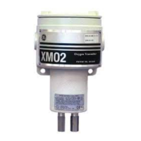
The XMO2 Transmitter The XMO2 Transmitter is self-contained, consisting of the oxygen
sensor and associated electronics. It requires a 24 VDC power input
@1.2 A maximum at power-up, and it provides a 4-20 mA analog
output signal that is proportional to the oxygen concentration of the
sample gas and has fully programmable zero and span points. Also
provided is an RS232 digital output for oxygen concentration,
background gas, and atmospheric pressure signals. Programming, and
calibration of the unit may also be performed via this interface.
All XMO2 transmitters include a 10 ft (3 m), 4-conductor cable for
connecting the power input and the 4-20 mA analog output. Optional
XMO2 accessories available from GE include:
• power/analog output cable lengths of up to 450 ft (137 m)
• 24 VDC power supply (Model PS5R-C24)
• 3-conductor cable with a DB9 (male or female) or DB25 (male or
female) connector for connecting the XMO2’s RS232 digital
output to external devices
The XMO2 is designed to be installed in a sample system as close as
possible to the process sample point. Thus, it is available in two
environmental packages:
• Weatherproof: NEMA-4X, IP66
• Explosion-proof: Class I, Groups A, B, C, D, Div. 1,
Cenelec EEx d II C T6, with gas inlet and outlet flame arrestors
The XMO2 Transmitter, which is shown in Figure 1-3 on page 1-7,
can be configured for the following standard oxygen ranges:
0 to 1% 0 to 25%
0 to 2% 0 to 50%
*
0 to 5% 0 to 100%
*
0 to 10% 80 to 100%
*
0 to 21% 90 to 100%
*
*Pressure compensation is required

 Loading...