September 2007
2-6 Installation
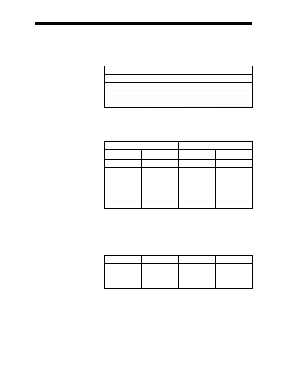
Cable Specifications Table 2-2 below shows the transmitter wiring connections using the
standard GE XMO2 4-wire cable [P/N X4(L), where L = length in ft].
This cable can be used for distances up to 450 ft (137 m).
If you are using your own cable to wire the XMO2, refer to Table 2-3
below for cable requirements.
Table 2-4 below shows the connections for the GE standard 3-wire
RS232 cable (P/N 704-667, 668, 669, or 670-L, where L = length in
ft), which is available with a DB-9 or a DB-25 connector (male or
female). This cable is available in standard lengths of 6 ft and 12 ft.
See the EIA-RS Serial Communications booklet (GE document
#916-054) for a more detailed discussion of RS232 wiring.
Note: See Figure B-4 on page B-4 for detailed drawings of the
standard GE cables described above.
Table 2-2: GE 4-Wire XMO2 Cable [P/N X4(L)]
Lead Color AWG Terminal
+24 VDC Line Red 22 TB1-1
–24 VDC Return Black 22 TB1-2
4-20 mA (+) White 22 TB1-3
4-20 mA (-) Green 22 TB1-4
Table 2-3: Non-GE Cable Requirements
MAX. CABLE LENGTH WIRE SIZE
ft m AWG mm
2
450 130 22 0.35
700 200 20 0.60
1,050 320 18 1.00
1,700 500 16 1.20
2,800 850 14 2.00
4,000 1,200 12 3.00
Table 2-4: GE 3-Wire RS232 Cable (P/N 704-6xx-L)
Lead Color AWG Terminal
RX Red 22 TB1-6
TX White 22 TB1-5
GND Green 22 TB1-2

 Loading...