September 2007
Outline and Installation Drawings B-3
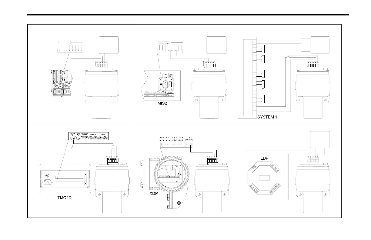
MIS1/MMS3 Connections (see User's Manual for details) MIS2 Connections (see User's Manual for details)
TMO2D Connections (see User's Manual for details) XDP Connections (see User's Manual for details)
123456
TB1
XMO2
PS5R-C24
(or equal)
RTN +24
REC
21
+-
A
AUX
+24V
76543
RTN
-+
B
12
8
MIS1/MMS3
387654
REC
A
-+
B
+- 1RTN
21
+24V2
AUX
nd
ine
eut
E
S
U
F
E
S
U
F
12
TB1
XMO2
456 3
PS5R-C24
RTN
(or equal)
+24
System 1 Connections (see User's Manual for details)
XMO2
465 3 2
TB1
1
XMO2
465 3 2
TB1
1
LDP Connections (see User's Manual for details)
XMO2
3654 12
+24
(or equal)
PS5R-C24
RTN
TB1
K1
K2
+
-
C
NO
N
C
C
N
O
N
C
H
L
G
n
d
24V
0V
-
+
+
-
124356
XMO2
+24
PS5R-C24
(or equal)
RTN
TB1
CS1.34 Data Acquisition PCB
12
3
4
5678 8765
4
3
21
TB1 TB2
12
3
4
5678
TB3
9
10
Same As TB1
Pins 2-4
Pins 2-4
Same As TB1
Pins 2-4
Same As TB1
Pins 2-4
Same As TB1
Pins 2-4
Same As TB1
Figure B-3: Interconnection Diagrams

 Loading...