Do you have a question about the GE XMO2 and is the answer not in the manual?
| Brand | GE |
|---|---|
| Model | XMO2 |
| Category | Transmitter |
| Language | English |
Details the fundamental characteristics and capabilities of the XMO2 Transmitter.
Explains the sensor's construction and the principles behind oxygen measurement.
Describes the available options for the XMO2 and the necessary sample system.
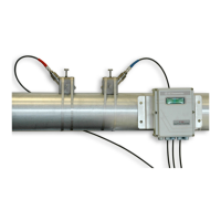
Provides step-by-step instructions for mounting the XMO2 transmitter in the sample system.
Details the process of setting up the sample system for the XMO2 transmitter.
Guides users through making the necessary electrical connections for the XMO2 system.
Explains how to energize the XMO2 transmitter and the initial warm-up procedure.
Details the methods available for calibrating the 4-20 mA analog output signal.
Describes the simplest method for initial field calibration using pushbutton controls.
Outlines the procedures performed at the factory for initial XMO2 calibration.
Lists the necessary materials and gases for performing field calibration.
Details the simplified calibration procedure using a single offset gas.
Explains the calibration process using both zero and span gases.
Guides on setting up a link between the XMO2 and a computer terminal.
Explains how to navigate through the XMO2's menu system during programming.
Describes the available options and their functions within the Basic Menu.
Instructions on how to access the General Menu for diagnostics and data entry.
Lists and describes the available menu options within the General Menu.
Used to set advanced calibration and operational parameters, including compensation.
Allows monitoring of various XMO2 input signals for diagnostic purposes.
Steps to access the Advanced Menu for system configuration and troubleshooting.
Configure gas type, background gas display, pressure type, and easy menu entry.
Set advanced calibration parameters like response type and compensation.
Details accuracy, linearity, repeatability, and response time of the XMO2.
Provides part numbers and options for ordering the XMO2 transmitter and accessories.
Lists the factory default programming options for the Basic and General Menus.
Describes the use of XMO2 for monitoring oxygen in inert gas blanketing systems.
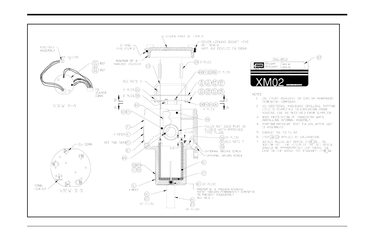
Provides assembly details and diagrams for the XMO2 transmitter unit.
Illustrates how to connect the XMO2 with other GE devices and systems.
Technical schematic diagram for the digital printed circuit board, sheet 1.
Flowchart detailing all submenus and options within the Basic Menu.
Menu map for calibrating pressure curve and grid settings in the General Menu.
Menu map for advanced setup, recorder calibration, RAM erase, and resume functions.
Flowchart for configuring error handling for terminal and mA output.