September 2007
A-2 Two Typical Applications
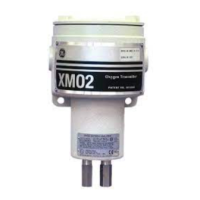
Equipment Used (cont.) The sample system in Figure A-1 on page A-1 consists of:
• an eductor to draw the sample from and return it to the vapor space
above the liquid in the storage tank
• a liquid separator/dump to remove condensable liquids
• a filter/coalescer for the removal of solid and liquid particulates
• automatic calibration gas solenoid valves for the automatic
calibration of the system on a timed basis
• flowmeters
• pressure gauges
All components are mounted on a painted steel plate that is usually
housed in a heated enclosure.
Note: An optional TMO2D display/controller (or similar device) is
required for automatic calibration of the XMO2.
Basic Operating
Procedure
The sample system should be located at or near the top of the storage
tank so that condensate can drip back into the tank. The gas used to
purge the tank provides the motive force in the eductor to pull a gas
sample from the vapor space above the hydrocarbon liquid into the
sample system. The sample gas, condensed liquids, and the inert gas
are all returned to the tank, making this is a closed-loop system. The
XMO2 is recalibrated periodically using the purge gas to zero the
instrument and ambient air (20.93% O
2
) to span the instrument. The
span gas can optionally be vented to atmosphere, so that air is not
introduced into the storage tank.
For this application the required calibration gases are:
• Zero Gas: N
2
or CO
2
(at least 99.95% pure)
• Span Gas: air (20.93% O
2
)
A typical XMO2 Calibration Sheet for this application is shown in
Figure 8-1 on page 8-6.
Previous Systems Electrolytic cells were once commonly used for this application.
However, such systems required extensive maintenance and frequent
manual calibration. In addition, the cells were easily damaged by
condensable liquids, requiring frequent cell replacement. As the
XMO2 provides continuous monitoring of the O
2
content with
maintenance-free operation, it is now the system of choice.

 Loading...