September 2007
4-4 Field Calibration
Preparing for Field
Calibration (cont.)
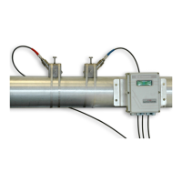
Figure 4-1: XMO2 Cover, Set Screw, and PCB
Note: The XMO2’s digital printed circuit board (PCB #703-1139) is
located directly below the cover (see Figure 4-1 above).
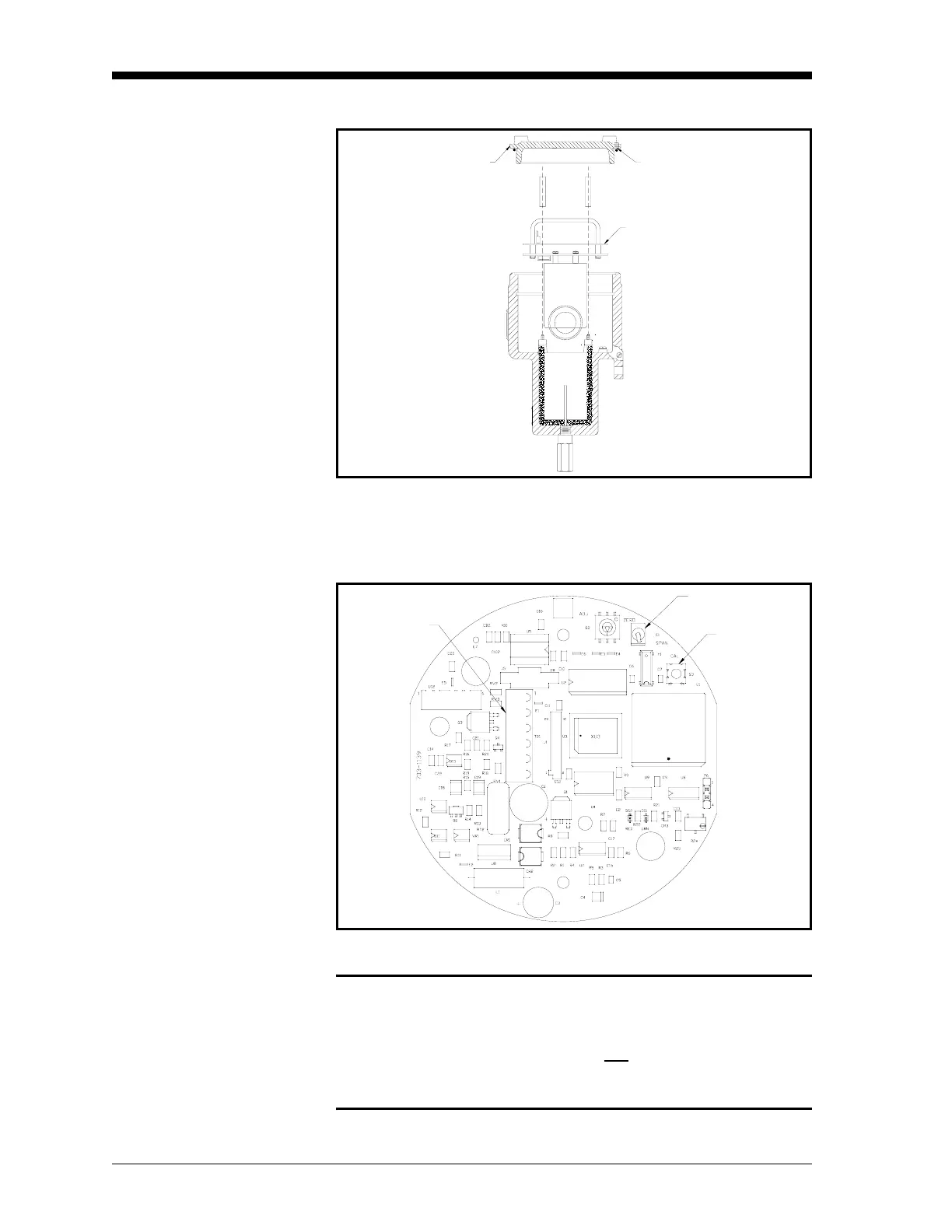
Figure 4-2: PCB #703-1139 Calibration Switches
Caution!
Switch S2, jumper P6, potentiometer R24, and
potentiometer R25 are also located on the XMO2 circuit
boards. However, these items are not
used for normal field
calibration. Never touch these items unless specifically
instructed to do so by GE.
Circuit Board
Set Screw
Cover
Switch S1
TB1
Switch S3

 Loading...