September 2007
7-28 Advanced Programming
mA OUTPUT Option The mA Output submenu is used to individually enable or disable
error handling for fifteen different 4-20 mA analog output error
conditions. In addition, the type of response to the error may be
specified. To program this menu, see Figure C-9 on page C-9 and
proceed as follows:
• The DriftCal Offset Error is generated when an error occurs during
an offset gas (one-gas) calibration.
If the Enable option was selected above, one or both of the following
additional prompts appear. Otherwise, skip over these prompts.
If the Force to Value option was selected above, the following
additional prompt appears. At that prompt, values from 0.00 to 25.00
may be entered. A 0.00 value forces a 0-3 mA output signal, and a
25.00 value forces a 22-26 mA output signal.
• The above programming sequence is repeated for all other error
conditions in this submenu (see the Terminal submenu on pages
7-22 to 7-27 for a list and description of all available options). As
usual, press
[NO] to move between the options and press [YES] or
[ENTER] to program the displayed option.
When ready, you may exit this submenu at the Done? option, as
described in the Terminal submenu on the previous page.
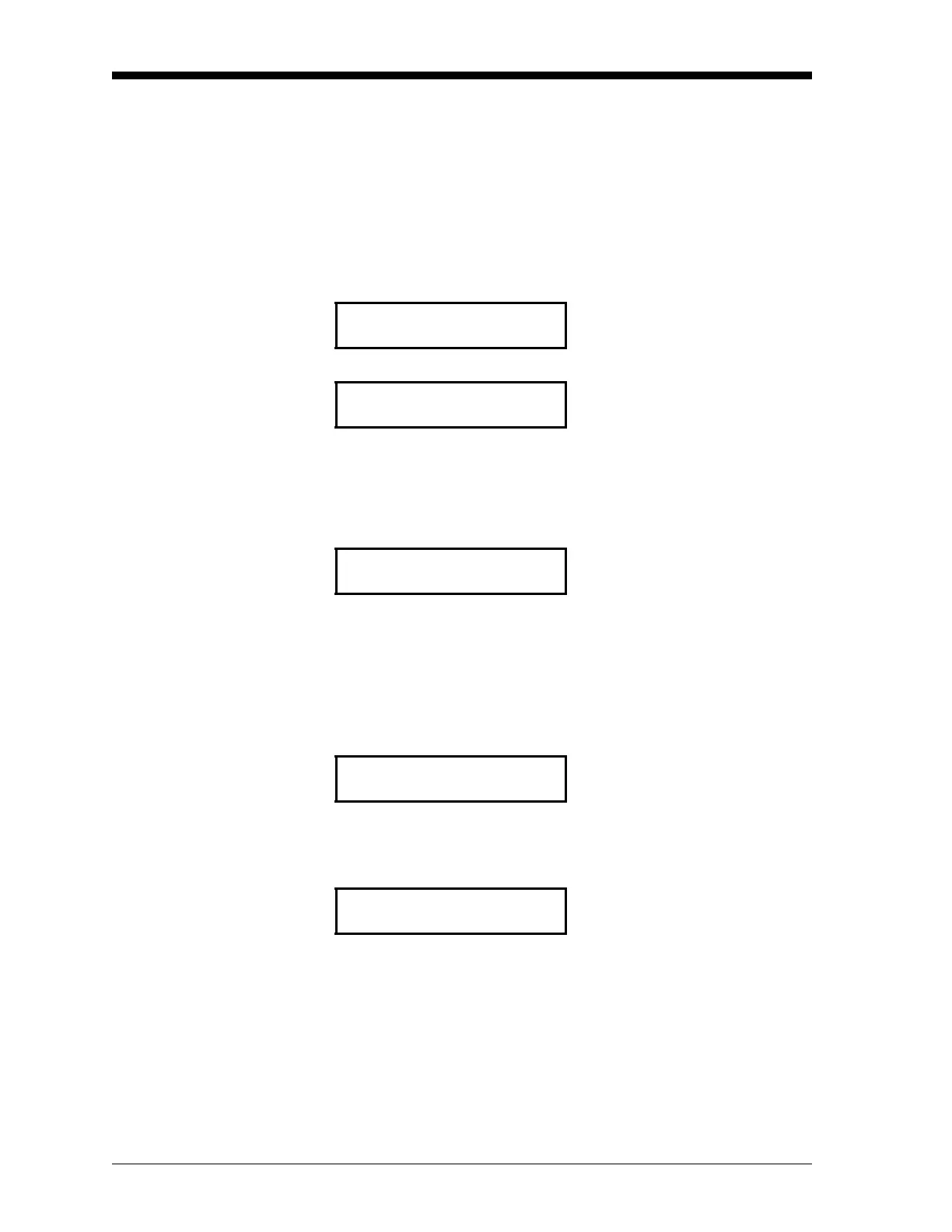
ENABLE/DISABLE ERRORS
Press [N] to skip this error, or
press
[Y] or [Enter] to set it.
DriftCal Offset Error?
DriftCal Offset Error response:
Press [N] to select the desired
option, then press
[Y] or [Enter] to
confirm your selection and move
to the next prompt.
disable [ENABLE]
Set mA Output Error response:
Press [N] to select the desired
option, then press
[Y] or [Enter] to
confirm your selection and move
to the next prompt.
[force high] force low force to value
Enter mA Output Error Value
To accept the current value, press
[Y] or [Enter]. To change the
current value, use the numeric
keys to enter a new value and
press
[Y] or [Enter] twice.
mA [xx.xx]
ENABLE/DISABLE ERRORS
Press [N] to move on to the next
error.
DriftCal Offset Error?