Installation 2-9
September 2007
Connecting to Other
Devices
This section discusses the interconnection the XMO2 transmitter with
other GE devices. The following devices are included:
• PS5R-C24 power supply
• TMO2D display
• LDP display
• XDP display
• Moisture Image/Monitor Series analyzers
• System 1 moisture analyzer
The PS5R-C24 Power
Supply
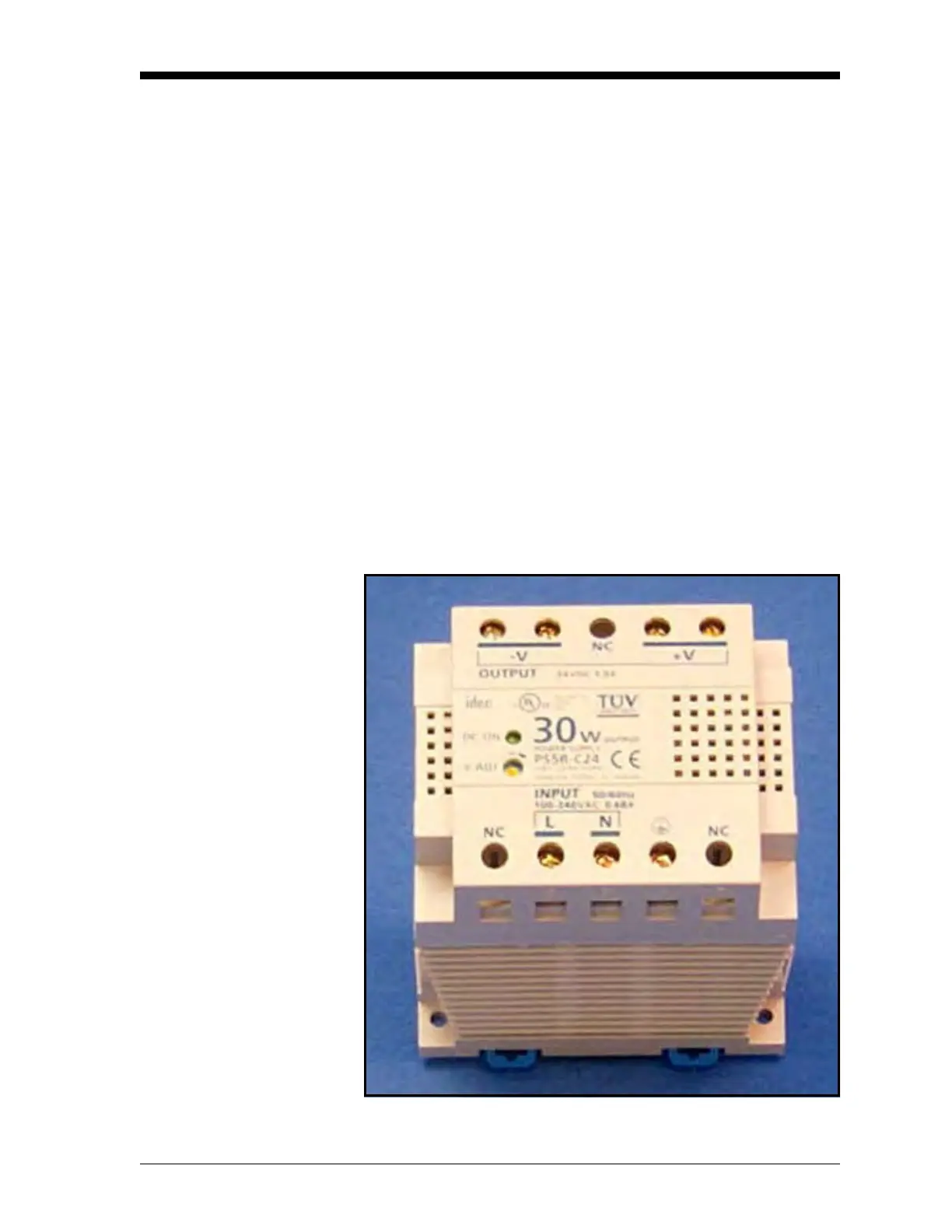
The GE PS5R-C24 power supply converts a 100-240 VAC input to
the required 24 VDC output. Figure 2-4 below shows the PS5R-C24
connections. As indicated, the AC input Line, Neutral and Ground
connections are made to the terminals along the bottom of the panel,
while the DC output +24V and -24V connections are made to the
terminals along the top of the panel. See the instructions provided
with the power supply for more details.
Figure 2-4: PS5R-C24 Power Supply Connections

 Loading...