139
5.2. Heating control and current (CT) application
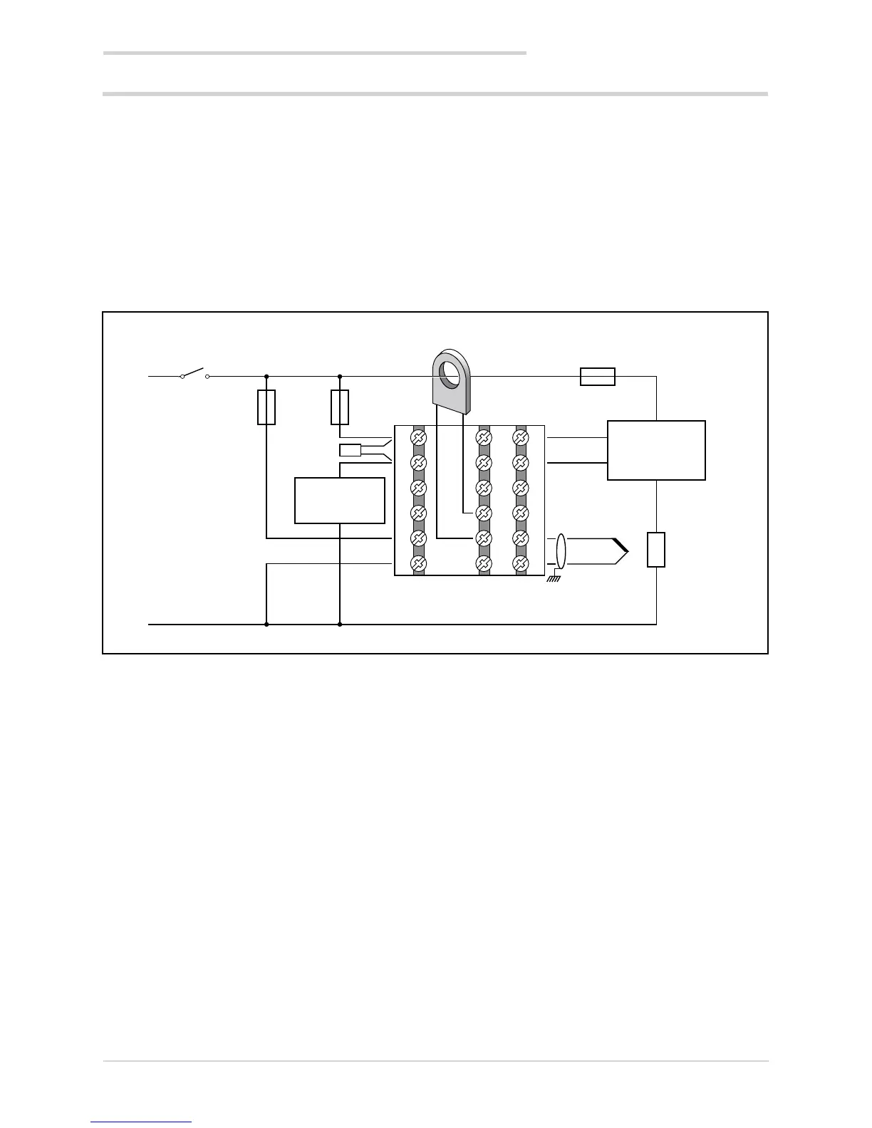
A 650 controller (model 650–D-R00-00100-1) controls a
heating element via a solid-state relay connected to a logic
output.
A TC sensor measures the temperature.
Each branch of the circuit is protected by a fuse.
The alarm relay is protected by a snubber.
A current transformer is connected to a dedicated input to
indirectly measure electrical consumption.
The following diagram shows the various connections.
One switch can control more than one controller.
With Quick Configuration you set:
• sensor type (TC);
• unit of measurement of temperature (°C);
• the logic output function (HEAT);
• the relay output function (ALRM1);
• the full-scale value of the CT1 current transformer (HI.
CT1)
• the setpoint, i.e. the temperature to be maintained
(SETP);
• the temperature value that trips the alarm (ALRM1).
5.2.1. Connection diagram
5. Examples and applicative notes
Current
transformer
Controller fuse
Solid state
relay
Heating
element
650 Controller
Fuse alarm
relay
Snubber
Alarm
relay
Heating element
fuse
6
5
4
3
2
1
7
8
9
10
11
12
19
20
21
22
23
24
+
-
T/C
L
N

 Loading...


