15
1.4. 1250 Controller
Main features
• Operator interface with large LCD Display, customi-
zable, with choice of colors
• Scrolling diagnostics messages, configurable, in the se-
lected language
• Easy, guided configuration, copy/paste parameters
even with power off
• Preventive maintenance with energy counters (kWh) and
load switching
• 16 function block applications
• Timer, setpoint and algorithm programmer for control-
ling motorized valves
• Advanced tuning of control parameters
• Different password levels
• Universal input configurable for thermocouples, resi-
stance thermometers, linear inputs
• Input from remote setpoint
• Relay, logic, isolated analog outputs
• Up to two TA inputs for interrupted load diagnostics
• RS485 serial communication in Modbus RTU
• Removable faceplate for immediate replacement
• Accuracy 0.2%, sampling time 60 ms
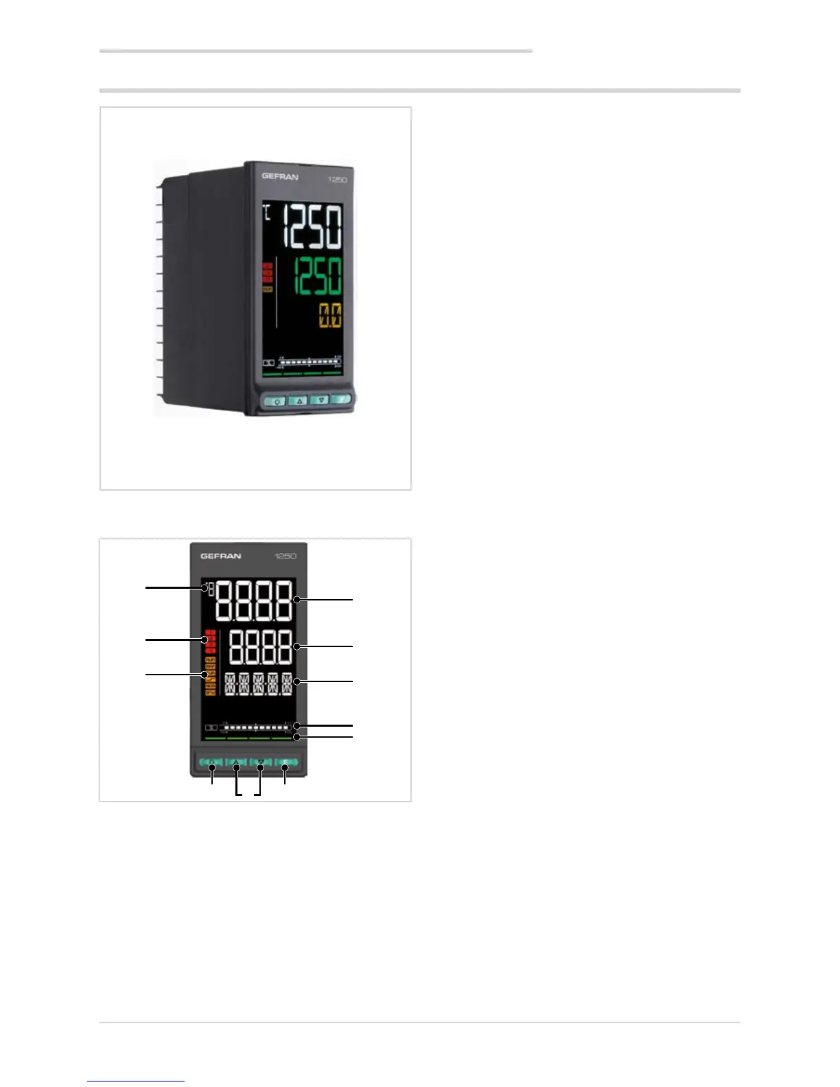
1.4.1. Display and keys
Figure 3 - Description of 1250 display and keys
1. Temperature unit of measurement or number of program
running.
2. State of outputs OUT1, OU2, OUT3, OUT4.
3. Controller function states:
• RUN = setpoint programmer active;
• _/- = setpoint ramp active;
• TUN = PID parameters tuning active;
• MAN = manual/automatic (off = automatic control,
on = manual control);
• REM = remote setpoint enabled;
• SP1/2 = setpoint active (off = setpoint 1,
on = setpoint 2).
4. Work mode key (manual/automatic) in standard mode.
A function can be assigned via parameter but1.
The key is active only when the display shows the pro-
cess variable.
5. Up/down keys: raise/lower the value of the parameter
displayed on the SV or PV display.
6. F key: lets you navigate among controller menus and
parameters. Confirms the parameter value and selects
the next parameter.
7. Key pressed signals.
8. Displays percentage of power or current, configurable
with parameter bArG.
9. Display F: parameters, diagnostics and alarm messages.
Configurable with parameter dS.F (default = setpoint).
10. SV display: parameter values. Configurable with para-
meter dS.SP (default = setpoint).
11. PV display: process variable.
Dimensions 48 × 96 × 80 mm (1/8 DIN)
1. GENERAL DESCRIPTION
1
2
3

 Loading...


