64
4. CONFIGURATION
4.7.1. tyPE - Selecting sensor type
Acronym Scrolling message Submenu Attributes
tyPE MAIN INPUT TYPE OF PROBE I.MAIN R W
The parameter shows and sets the sensor type of the main input.
The functions for calibrating Custom sensors are on the US.CAL menu.
When a 4...20 mA input is used and the current is less than 2 mA, an Err message is generated and the relay state speci-
fied with the FAUL.T parameters is activated.
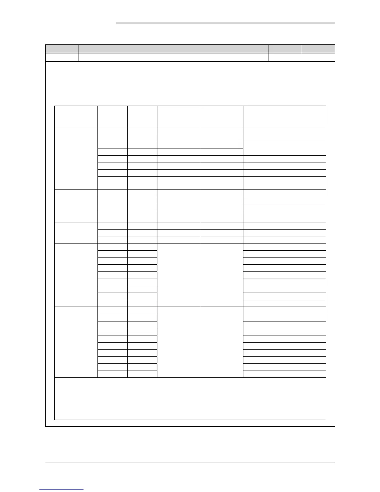
The table shows the scale limits for each sensor type or input based on the set number of decimals.
Sensor type Sensor
Unit of
measure-
ment
Scale limits for
DEC.P = 0
Scale limits for
DEC.P = 1
Error @ 25°C
Thermocouple
J °C 0...1000 0.0...999.9 < 1.6°C
K °C 0...1300 0.0...999.9
R °C 0...1750 0.0...999.9 with scale 0...1750 °C: < 2°C
(T > 100 °C)
S °C 0...1750 0.0...999.9
T °C -200...400 -199.9...400.0 < 1.6°C
C °C 0...2300 0.0...999.9 < 1.6°C
D °C 0...2300 0.0...999.9 < 1.6°C
Pt20Rh
Pt40Rh
°C 0...1880 0.0...999.9 < 5.1°C (T>1000°C)
Infrared
characteristic
of the
Tc K model
see note
1 °C 10...70 10.0...70.0 maximum error 0.5°C
2 °C 60...120 60.0...120.0 maximum error 0.5°C
3 °C 115...165 115.0...165.0 maximum error 0.5°C
4 °C 140...260 140.0...260.0
maximum error 0.5°C
Resistance
thermometer
PT100 °C -200...850 -199.9...850.0 < 1°C
PT100 °C -50...100 -50.0...100.0
JPT100 °C -200...600 -199.9...850.0 < 1°C
Voltage /Current
0...60 mV
-1999...9999 -199.9...999.9
0...20 mA
4...20 mA
0...10 V
2...10 V
0...5 V
1...5 V
0...1 V
0.2...1 V
Custom
RTD
-1999...9999 -199.9...999.9
0...60 mV
0...20 mA
4...20 mA
0...10 V
2...10 V
0...5 V
1...5 V
0...1 V
0.2...1 V
Nota: the infrared temperature sensor has an output in voltage for direct connection to the input terminals of the temperature con-
troller. An external thermometer is needed in order to correct the sensor error.
After identifying the work temperature range (for example, 140 – 260°C), set an SP near the minimum scale value, and after rea-
ching it make a note of value A1 indicated by the instrument and of value A2 indicated by the external thermometer. Set an SP near
the maximum scale value, and after reaching it make a note of value B1 indicated by the instrument and of value B2 indicated by
the external thermometer. Enable 4-point linearization (see Correcting 4-point input) and enter the four requested values (A1, B1
and A2, B2)..

 Loading...


