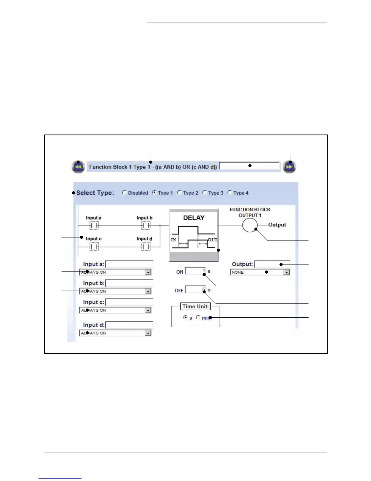
1. Button to return to previous function block.
2. Number of function block and type of logic operations
run.
3. Name of function block. You can insert an optional
descriptive name of the function block.
4. Button to go to next function block..
5. Output value when result of function operations is true.
6. Graph of DELAY TIMER.
7. Name of output. You can insert an optional descriptive
name of the output.
8. Type or variable of activated output.
9. Duration of ON delay.
10. Duration of OFF delay.
11. Unit of measurement of delays (seconds or minutes).
12. Type or variable of input evaluated for input d.
The Input d box is used to insert an optional descripti-
ve name of input d.
13. Type or variable of input evaluated for input c.
14. Type or variable of input evaluated for input b.
The Input d box is used to insert an optional descripti-
ve name of input b.
15. Type or variable of input evaluated for input a.
The Input a box is used to insert an optional descriptive
name of input a.
16. Graph of logic operation run. The input boxes also
show the value that the input must assume in order to
be considered “true”.
17. Selection of logic function applied to function block.
5. Examples and applicative notes
LO ALARM (Lou sensor input state)
HI ALARM (HIGH sensor input state)
ERR ALARM (Err sensor input state)
SBR (Sbr sensor input state)
STATUS AUTOMATIC
STATUS MANUAL
STATUS LOCAL
STATUS REMOTE
Controller models with programmer also have:
PROGRAMMER IN HBB ALARM
PROGRAMMER IN RUN
PROGRAMMER IN HOLD
PROGRAMMER IN READY
PROGRAMMER IN END
STEP EVENT 1
STEP EVENT 2
STEP EVENT 3
STEP EVENT 4

 Loading...


