141
5.3. Remote setpoint input
The value of the analog remote setpoint input is shown in
the parameter SETPR.
The function can be:
• display only (with settable alarms if required);
• process variable (PV) setpoint if the controller is in
REMOTE mode;
• POWER setpoint if the controller is in MANUAL and
REMOTE mode
5.4. 4-point input correction
The 4-point input correction lets you correct the read of the
main input and/or of the remote setpoint input by setting four
values: A1, B1, A2 e B2.
To enable the function, set parameter Lin to 4.POIN (I.MAIN
menu or I.SPR menu).
The limitations are:
• B1 must always be larger than A1;
• B1-A1 must be 25% larger than the full scale of the
selected sensor.
The setting is limited to the preset scale LO.SCL... HI.SCL
on the I.MAIN menu (or I.SPR). The offset function (parame-
ter OF.SCL, I.MAIN menu) remains enabled.
By using this function for linear scales (60 mV, 1 V, 5 V, 10 V,
20 mA) you can invert the scale.
The four values are set on the LINRZ menu as follows:
• A1 = STP.00
• B1 = STP.01
• A2 = STP.02
• B2 = STP.03
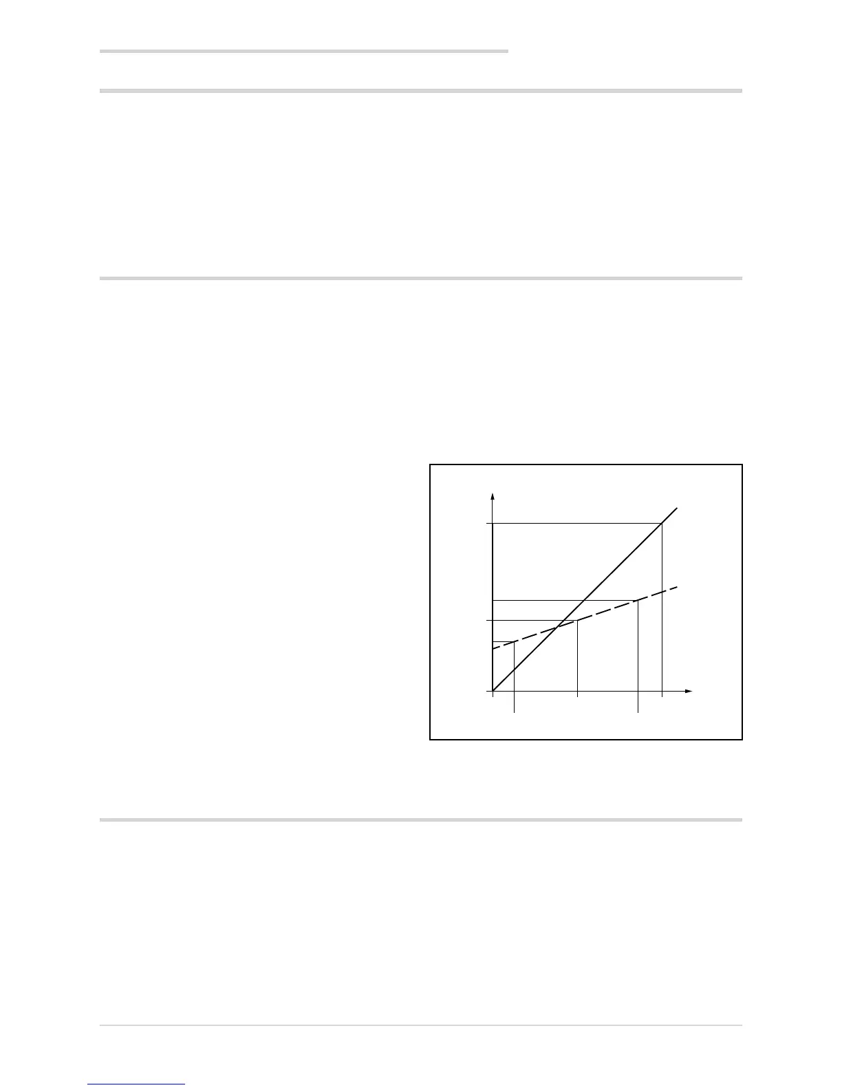
Example
Select Pt100 input with Lin = 4.POIN to obtain an RTD sen-
sor with 4-point input correction.
Input Pt100 with:
• Lin = 4.POIN (Pt100 natural scale -200...850),
• DEC.P = 0
• LO.SCL = 0
• HI.SCL = 400
The maximum and minimum scale values of the input are
shown by read-only parameters LO.SPR and HI.SPR on the
user configuration menu.
The parameter SETPR is shown in read-only on the user
configuration menu.
The reference points on the real curve (input) are:
• A1 = STP.00 = 50,
• B1 = STP.01 = 350,
B1-A1 = 300, which is larger by 212,5 (25% of 850).
The corresponding points on the corrected curve (indica-
tion) are:
• A2 = STP.02 = 120,
• B2 = STP.03 = 220.
With the corrected curve an input value of 200 is displayed
as 170.
Figure 17 - Diagram of 4-point input correction, for the
example (Pt100 input)
5.5. Current inputs
The values of current inputs CT1 and CT2 are shown in
parameters CURR1 and CURR2.
These values are used in generic alarms AL1… AL4 and
especially for the HB alarm
The maximum scale value of the input is shown by para-
meter HI.CT1 on submenu I.CT1 for CT1, and by parameter
HI.CT2 on submenu I.CT2 for CT2.
5. Examples and applicative notes
Indication
Without
correction
With
correction
Input
A1 = 50
A2 = 120
B2 = 220
B1 = 350
0
0
400
400
200
170

 Loading...


