Virgin circuit
When control unit (ECU) and decoder are not pro-
grammed, the following conditions occur:
- Key switch set to «OFF»:
Deterrent flashing inactive.
- Key switch set to «ON»:
Ignition and injection disabled and LED on with
solid light.
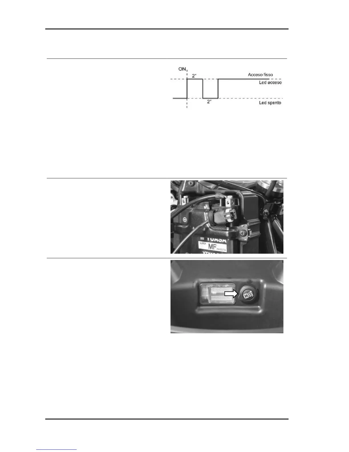
When the key switch is set to "ON", the LED
switches on as shown in the figure.
The LED is turned on by the decoder.
Specific tooling
020460Y Scooter diagnosis and tester
To connect the diagnostic tester, open the battery
inspection port and pull out the EMS diagnosis
socket. Remove the protection cap and connect
the tester terminal.
Power the diagnostic tester by connecting the ter-
minals to the battery poles, or the specific connec-
tor to the socket inside the helmet compartment.
Electrical system GP 800 i.e.
ELE SYS - 28

 Loading...