DTC
1-1
(MAP SENSOR
VOLTAGE)
• Before starting the inspection, check for loose or
poor contact
on
the sensor unit 5P (Black) connector
and recheck
the
OTC.
1. MAP Sensor System Inspection 1
Turn the ignition switch
ON
and engine stop switch
"0".
Check the
MAP
sensor with the MCS tester.
Is about O Vindicated?
YES -
GO
TO
STEP
2.
NO - • Intermittent failure
• Loose or poor contact
on
the sensor
unit
5P
(Black) connector
2.
MAP Sensor System Inspection
2
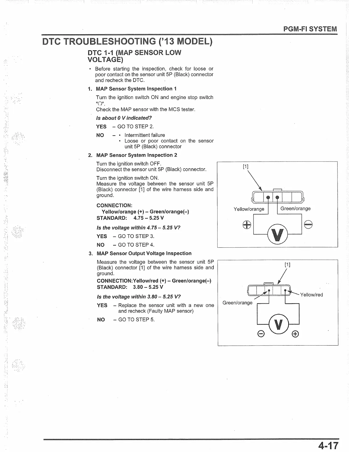
Turn the ignition switch OFF.
Disconnect the sensor unit
5P
(Black) connector.
Turn the ignition switch
ON.
Measure the voltage between the sensor unit
5P
(Black) connector
[1]
of the wire harness side and
ground.
CONNECTION:
Yellow/orange(+) - Green/orange(-)
STANDARD:
4.75-5.25
V
Is the voltage within
4.
75
- 5.25
V?
YES -
GO
TO
STEP
3.
NO -
GO
TO
STEP
4.
3. MAP Sensor Output Voltage Inspection
Measure the voltage between the sensor unit
5P
(Black) connector [1] of the wire harness side and
ground.
CONNECTION:Yellow/red
(+) -
Green/orange(-)
STANDARD:
3.80-5.25
V
Is the voltage within 3.80 - 5.25
V?
YES -
Replace the sensor unit with a new one
and
recheck (Faulty MAP sensor)
NO -
GO
TO
STEP
5.
SYSTEM
[1]
.-,/
 Loading...