PGM-FI SYSTEM
4-22
DTC
8-1
(TP SENSOR LOW VOLTAGE)
• Before starting the inspection, check for loose or
poor contact
on
the sensor unit
SP
(Black) connector
and recheck the
OTC.
1. TP Sensor System Inspection
Turn the ignition switch
ON
and engine stop switch
"O".
Check the TP sensor with the MCS tester when the
throttle fully closed.
Is about O Vindicated?
YES -
GO
TO STEP
3.
NO -
GO
TO
STEP
2.
2. TP Sensor Inspection
Check that TP. sensor voltage
is
increasing
uninterrupted when moving the throttle from fully
closed to fully opened using the data list menu of the
MCS tester.
Does the voltage increase continuously?
YES - •
Intermittent failure
• Loose or poor contact
on
the sensor
unit
SP
(Black) connector
NO
-
Replace the sensor unit with a new one
and recheck (Faulty
TP
sensor).
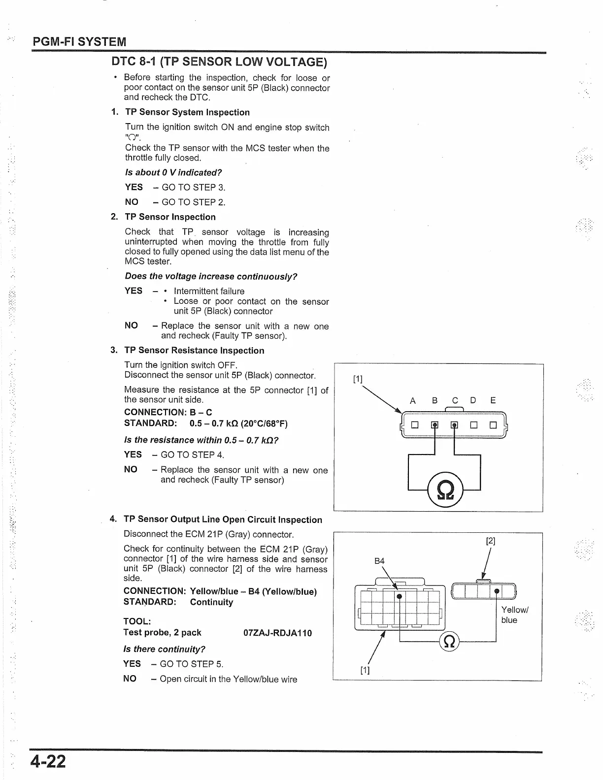
3. TP Sensor Resistance Inspection
Turn the ignition switch OFF.
Disconnect the sensor unit
SP
(Black) connector.
Measure the resistance at the
SP
connector
[1]
of
the sensor unit side.
CONNECTION:
B -
C
STANDARD: 0.5 - 0.7 kO (20°C/68°F)
Is the resistance within 0.5 - 0.7
k!l?
YES -
GO
TO STEP
4.
NO -
Replace the sensor unit with a new one
and recheck (Faulty
TP
sensor)
4. TP Sensor Output Line Open Circuit Inspection
Disconnect the ECM
21
P (Gray) connector.
Check for continuity between the
E'.CM
21
P (Gray)
connector
[1]
of the wire harness side and sensor
unit
SP
(Black) connector
[2]
of the wire harness
side.
CONNECTION: Yellow/blue -
84
(Yellow/blue)
STANDARD: Continuity
TOOL:
Test probe, 2 pack 07ZAJ-RDJA 110
Is there continuity?
YES -
GO
TO STEP
5.
NO -
Open circuit
in
the Yellow/blue wire
[1]
[1]
[2]
Yellow/
blue

 Loading...