PGM-FI SYSTEM
4-36
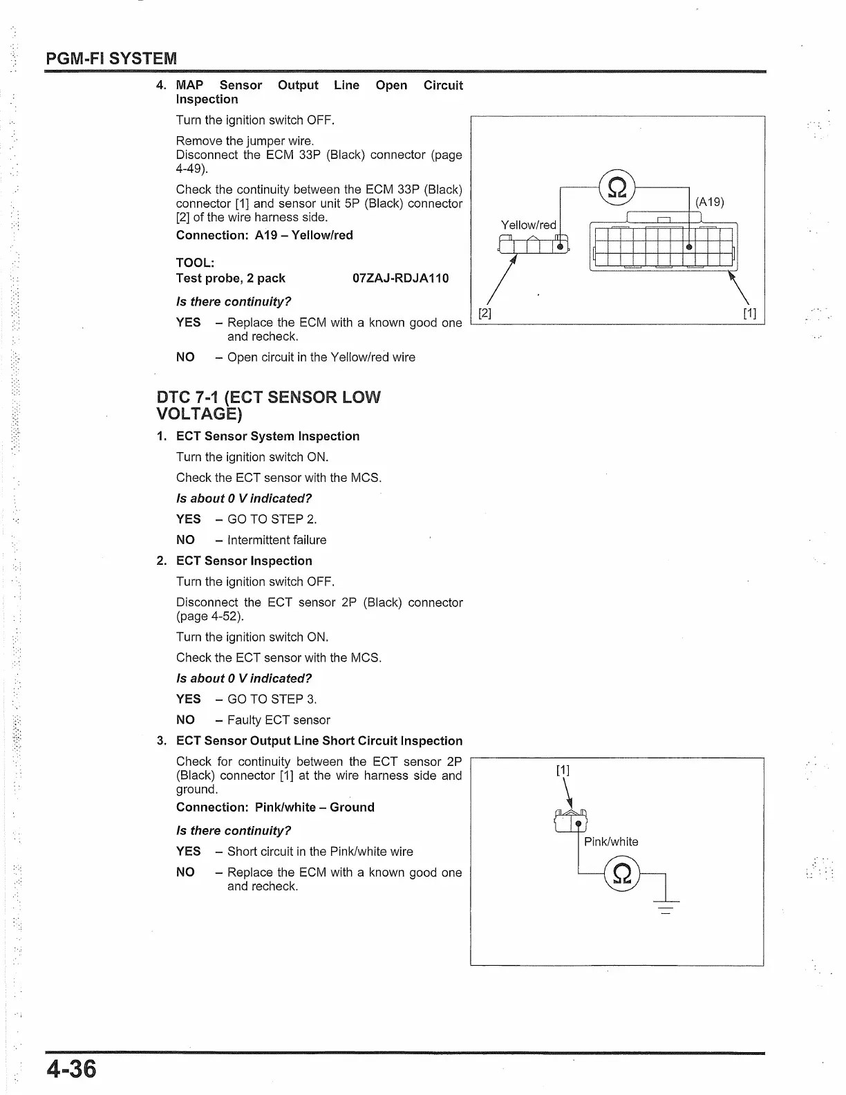
4. MAP Sensor Output Line Open Circuit
Inspection
Turn the ignition switch OFF.
Remove the jumper wire.
Disconnect the ECM 33P (Black) connector (page
4-49).
Check the continuity between the ECM 33P (Black)
connector [1] and sensor unit
5P
(Black) connector
[2] of the wire harness side.
Connection: A19 - Yellow/red
TOOL:
Test probe, 2 pack
07ZAJ-RDJA 110
Is there continuity?
YES - Replace the
ECM
with a known good one
and recheck.
NO - Open circuit
in
the Yellow/red wire
DTC 7
-1
(ECT SENSOR
LOW
VOLTAGE)
1. ECT Sensor System Inspection
Turn the ignition switch
ON.
Check the ECT sensor with the MCS.
Is about O Vindicated?
YES -
GO
TO STEP
2.
NO - Intermittent failure
2. ECT Sensor Inspection
Turn the ignition switch OFF.
Disconnect the ECT sensor 2P (Black) connector
(page 4-52).
Turn the ignition switch
ON.
Check the ECT sensor with the MCS.
Is about O Vindicated?
YES -
GO
TO STEP
3.
NO - Faulty ECT sensor
3.
ECT Sensor Output Line Short Circuit Inspection
Check for continuity between the ECT sensor 2P
(Black) connector [1] at the wire harness side and
ground.
Connection: Pink/white - Ground
Is there continuity?
YES - Short circuit
in
the Pink/white wire
NO - Replace the
ECM
with a known good one
and recheck.
(A19)
Yellow/red
[2] [1]
[1]
\
Pink/white
 Loading...