PGM-FI SYSTEM
DTC TROUBLES OOTING {AFTER '13
MO
L)
4-34
OTC
1-1
(MAP SENSOR LOW
VOLTAGE)
1.
MAP Sensor System Inspection
Turn the ignition switch
ON.
Check the MAP sensor with the MCS.
Is about O Vindicated?
YES -
GO
TO
STEP
2.
NO - Intermittent failure
2.
Sensor Unit Power Line Inspection
Check the sensor unit power line inspection (page
4-33).
Is the sensor unit
power
line normal?
YES -
GO
TO STEP
3.
NO - Replace or repair the abnormal circuit.
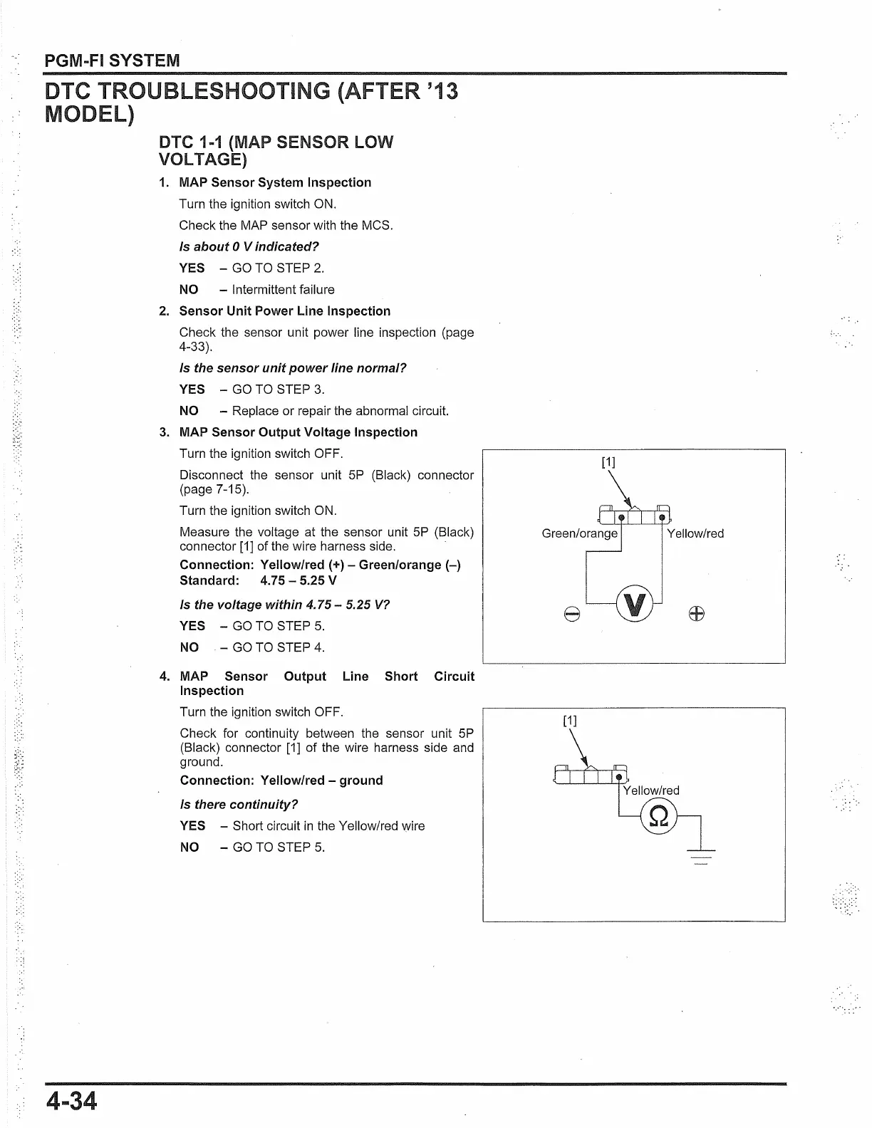
3.
MAP Sensor Output Voltage Inspection
Turn the ignition switch OFF.
Disconnect the sensor unit 5P (Black) connector
(page 7-15).
Turn the ignition switch ON.
Measure the voltage at the sensor unit 5P (Black)
connector
[1]
of the wire harness side.
Connection: Yellow/red (+) - Green/orange(-)
Standard: 4.75 - 5.25 V
Is the voltage within 4.75 - 5.25
V?
YES -
GO
TO
STEP
5.
NO -
GO
TO
STEP
4.
4.
MAP Sensor Output Line Short Circuit
Inspection
Turn the ignition switch OFF.
Check for continuity between the sensor unit
5P
(Black) connector [1] of the wire harness side and
ground.
Connection: Yellow/red - ground
Is there continuity?
YES -
Short circuit
in
the Yellow/red wire
NO -
GO
TO
STEP
5.
[1]
Yellow/red
e
[1]
Yellow/red
 Loading...