LIGHTS/METERS/SWITCHES
HAND
21-24
SWITC
ES
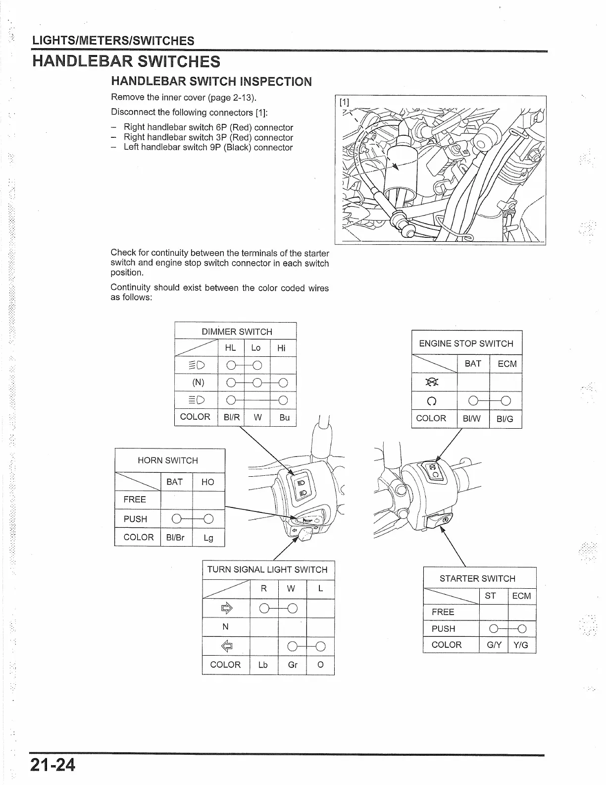
HANDLEBAR SWITCH INSPECTION
Remove the inner cover (page 2-13).
Disconnect the following connectors
[1]:
- Right handlebar switch 6P (Red) connector
- Right handlebar switch
3P (Red) connector
- Left handlebar switch 9P (Black) connector
Check for continuity between the terminals
of
the starter
switch and engine stop switch connector
in
each switch
position.
Continuity should exist between the color coded wires
as follows:
DIMMER SWITCH
COLOR BI/R W
Bu
HORN SWITCH
BAT HO
FREE
PUSH
COLOR Bl/Br
Lg
TURN SIGNAL LIGHT SWITCH
L
N
COLOR
Lb
Gr
0
ENGINE STOP SWITCH
BAT ECM
0
COLOR BI/W BI/G
STARTER SWITCH
ST
ECM
FREE
.-
PUSH
COLOR G/Y Y/G
 Loading...