REMOVAL/INSTALLATION
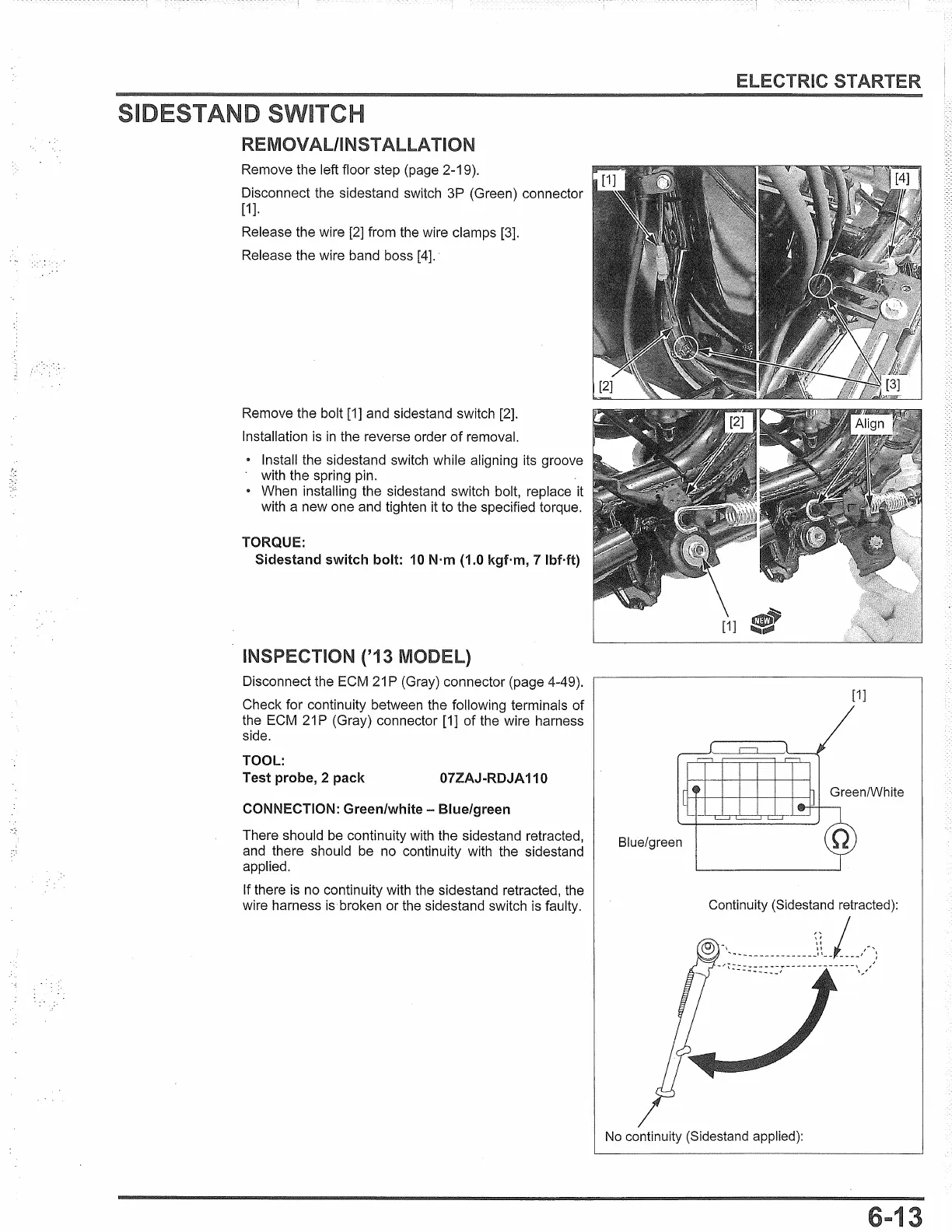
Remove the left floor step (page 2-19).
Disconnect the sidestand switch 3P (Green) connector
[1
].
Release the wire [2] from the wire clamps [3].
Release the wire band boss
[4].
·
Remove the bolt [1] and sidestand switch [2].
Installation
is
in
the reverse order
of
removal.
• Install the sidestand switch while aligning its groove
with the spring pin.
• When installing the sidestand switch bolt, replace it
with a new one and tighten it to the specified torque.
TORQUE:
Sidestand switch bolt:
10
N·m (1.0 kgf·m, 7 lbMt)
INSPECTION ('13 MODEL)
Disconnect the ECM
21
P (Gray) connector (page 4-49).
Check for continuity between the following terminals of
the ECM
21
P (Gray) connector [1] of the wire harness
side.
TOOL:
Test probe, 2 pack
07ZAJ-RDJA 110
CONNECTION: Green/white - Blue/green
There should be continuity with the sidestand retracted,
and there should be no continuity with the sidestand
applied.
If there is no continuity with the sidestand retracted, the
wire harness is broken or the sidestand switch
is
faulty.
ELECTRIC
[1]
Blue/green
Continuity (Sidestand retracted):
,,
I
-
ti
~
'
...
~
...
--------------~~-- ,
____
,,
.....
~
- r ~=::
:: ::
:
:;--
--
..
- -
---
--
-\;,,:'
No
continuity (Sidestand applied):
 Loading...