HUAWEI NetEngine40E Universal ServiceRouter
Hardware Description
4 NE40E-X3 Chassis Overview
Huawei Proprietary and Confidential
Copyright © Huawei Technologies Co., Ltd.
4.3 Heat Dissipation System
This section describes the appearance, functions, and specifications of the heat dissipation
system.
4.3.1 System Air Channel
This section describes the NE40E-X3's system air channel.
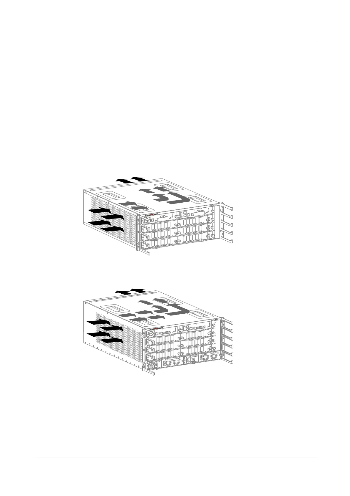
The NE40E-X3 draws in air from the left and exhausts air from the rear. The air intake vent is
located at the left side of the chassis and the air exhaust vent is located at the rear of the
chassis.
The fan module of the NE40E-X3 is located at the air exhaust vent. The system draws in air
for heat dissipation, as shown in Figure 4-12 and Figure 4-13.
Figure 4-12 Air flow in the NE40E-X3 DC chassis
Figure 4-13 Air flow in the NE40E-X3 AC chassis
The heat dissipation system consists of the following components:
One fan module
An air intake vent and an air exhaust vent
An air filter
Fans on power modules
 Loading...