Secondary I/O Drawer Operator Panel Behavior During Power-On
After Connecting ac Power (dc Power in a dc-powered System)
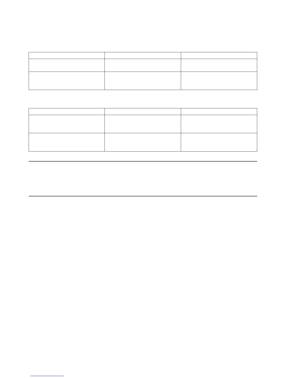
Drawer State Power LED Drawer Operator Panel Display
Standby Off Display shows a temporary drawer
number of the form *0n
Receive firmware command to power
on
On solid Message based on “Secondary I/O
Drawer Operator Panel Message
Hierarchy” on page 26.
After Power is Removed Because of a Shutdown
Drawer State Power LED Drawer Operator Panel Display
Standby Off Message based on “Secondary I/O
Drawer Operator Panel Message
Hierarchy” on page 26
Receive firmware command to power
on
On solid Message based on “Secondary I/O
Drawer Operator Panel Message
Hierarchy” on page 26
Logical and Physical Locations
The Model M80 and Model 6M1 systems use physical location codes in conjunction with AIX location
codes to provide mapping of the failing field replaceable units (FRUs). The location codes are produced by
the system unit’s firmware and the AIX operating system.
Physical Location Codes
Physical location codes provide a mapping of logical functions in a platform (or expansion sites for logical
functions, such as connectors or ports) to their specific locations within the physical structure of the
platform.
Location Code Format
The format for the location code is a string of alphanumeric characters separated by a dash (-), slash (/),
pound sign (#) or period (.) character. The base location is all of the information preceding the slash (/) or
pound sign (#). The base location identifies a device that is connected to or plugged into the parent.
Extended location information follows the slash (/). Extended location information identifies a device that is
part of the parent, a connector, or a cable. Cable information follows the pound sign (#). Cable information
identifies a cable that is connector to parent. The following are examples:
v P1-C1 identifies a processor card C1 plugged into planar P1.
v P1-M1 identifies a memory card M1 plugged into planar P1.
v P1-K1 identifies a keyboard attached to K1 on planar P1.
v P1/S1 identifies serial port 1 controller on planar P1, the connector for serial port 1, or the cable
attached to serial port 1.
v P1-I2/E3 identifies a Ethernet controller 3 on the card in slot 2 (I2) on planar P1, the connector for
Ethernet controller 3, or the cable attached to Ethernet controller 3.
v P1-I2#E3 identifies the cable attached to Ethernet controller 3 on the card in slot 2 (I2) on planar P1.
The
period (.) identifies sublocations (DIMMs on a memory card, SCSI addresses, cables). The following
are examples:
v P1-M1.4 identifies DIMM 4 on memory card 1 plugged into planar P1.
v P1-C1.1 identifies processor 1 plugged into processor card 1 which is plugged into planar P1.
28 Service Guide
 Loading...


