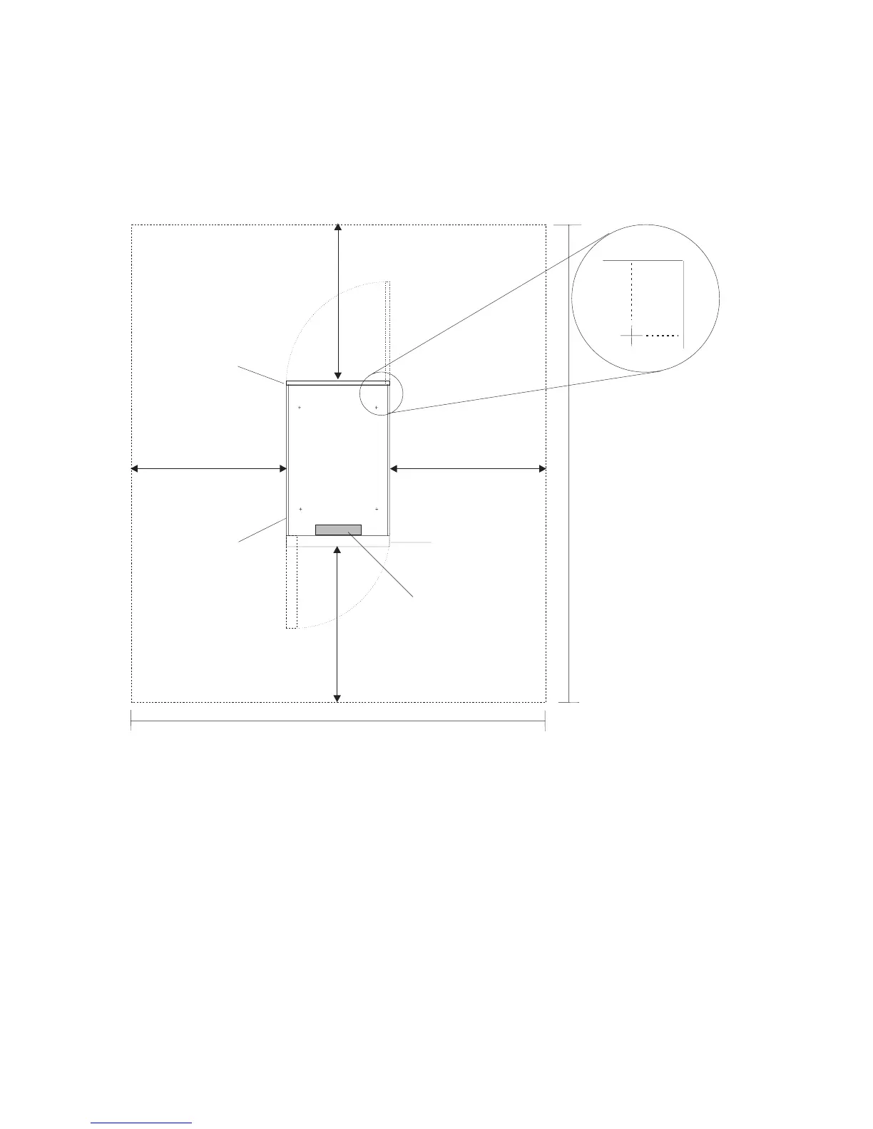
System Service Clearances
The amount of space required during service is indicated by the dotted line in the following figure.
For multiple racks placed side by side, the left and right clearances apply only to the leftmost and
rightmost rack.
Rack Configuration
2474 mm (97.4 in.)
2921 mm
(115 in.)
915 mm
(36 in.)
915 mm
(36 in.)
915 mm (36 in.)
915 mm (36 in.)
Front
Caster
Location
Front cover
thickness
58 mm (2.4 in.)
Rear cover
thickness
20 mm (0.8 in.)
Side cover
thickness 2x
10 mm (0.4 in.)
(4.8)121
(3.1)
80
Cable opening
310 mm (12.2 in.)
x 50 mm (2 in.)
Note: Rack units are large and heavy and are not easily moved. Because maintenance activities require
access at both the front and back, allow for extra room. The footprint shows the radius of the
swinging doors on the I/O rack. The figure shows the minimum space required.
62 Service Guide
 Loading...


