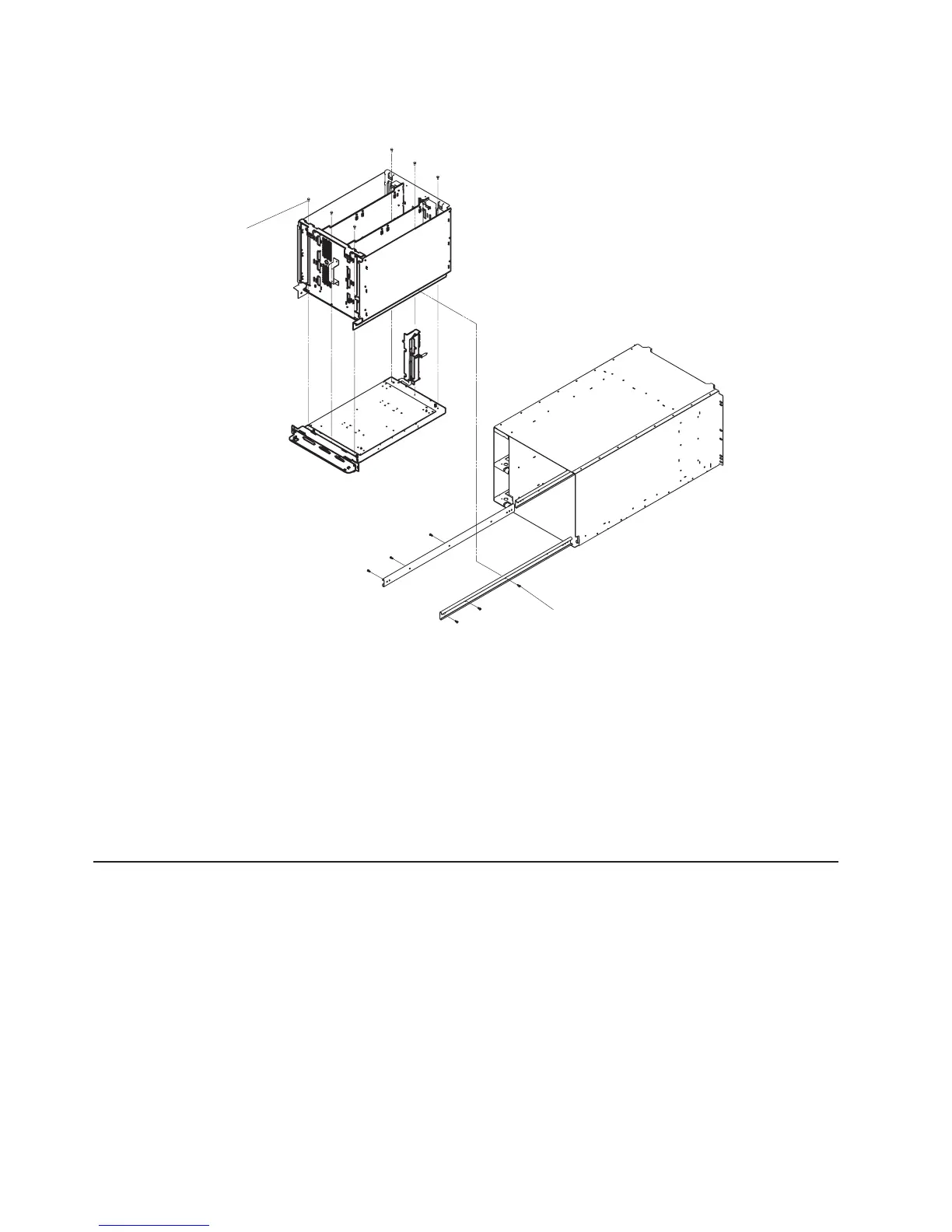
15. Remove the six cage-to-slide screws (1) to separate the CEC card-cage from the drawer enclosure,
as shown in following figure.
1
2
16. Place the CEC card-cage on a suitable work surface.
Attention: Make sure adequate support is given to the edges of the CEC backplane so that
clearance is allowed for components attached to it. Under no circumstances must any of the
components (such as modules or heat sinks) come in contact with the work surface. These attached
components will not support the weight of the CEC card-cage without sustaining some damage.
17. Reach in through the top of the card-cage/backplane assembly to remove the 6 cage-to-backplane
screws (2) and carefully lift the CEC card-cage off the CEC backplane. Refer to the previous figure.
Replacement
Replace in reverse order.
I/O Drawer Backplane Assembly
Removal
1. Turn off power as described in “Powering Off the System” on page 415.
2. Place the I/O drawer in the rear service position, as described in “Rear Service Position” on page
463.
3. Remove the two thumbscrews and remove the back cover.
442 Service Guide
 Loading...


