4.9 STATIC CHARGE DETECTION
Electrostatic charge is a deficiency or excess of electrons on an
ungrounded surface. Such charges are usually generated on
poor conductors of electricity such as plastics, synthetic
fibers, and paper during handling or processing of these
materials. Once these charges accumulate, they do not dis-
sipate readily because of the excellent insulating character-
istics of the materials involved.
Static charge build-up can be a problem with integrated cir-
cuits, especially with those of the CMOS variety. While these
devices, which operate at high impedance levels, often have
static protection built in, it is best to properly protect them
during transit or storage. For that reason, such KS are usually
shipped and stored in anti-static tubes.
A primary consideration, then, is the degree of static protec-
tion afforded by the anti-static tube. A comparison among
various tubes can be set up to test the variations in charge
build-up as a particular IC slides the length of the tube. The
charge value will, of course, be measured by the Model 617
being operated in the coulombs function.
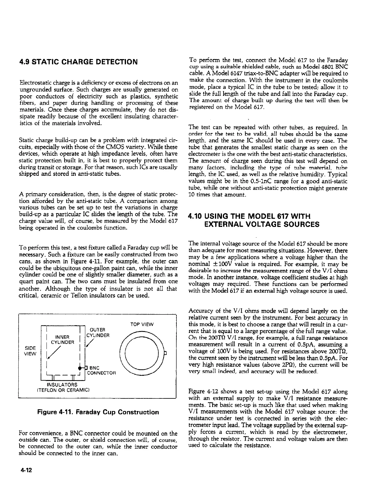
To perform this test, a test fixture called a Faraday cup will be
necessary. Such a fixture can be easily constructed from two
cans, as shown in Figure 4-11. For example, the outer can
could be the ubiquitous one-gallon paint can, while the inner
cylinder could be one of slightly smaller diameter, such as a
quart paint can. The two cans must be insulated from one
another. Although the type of insulator is not all that
critical, ceramic or Teflon insulators can be used.
INSULATORS
iTEFLON OR CERAMIC)
Figure 4-11. Faraday Cup Construction
For convenience, a BNC connector could be mounted on the
outside can. The outer, or shield connection will, of course,
be connected to the outer can, while the inner conductor
should be connected to the inner can.
To perform the test, connect the Model 617 to the Faraday
cup using a suitable shielded cable, such as Model 4801 BNC
cable. A Model 6147 triax-to-BNC adapter will be required to
make the connection. With the instrument in the coulombs
mode, place a typical IC in the tube to be tested; allow it to
slide the full length of the tube and fall into the Faraday cup.
The amount of charge built up during the test will then be
registered on the Model 617.
The test can be repeated with other tubes, as required. In
order for the test to be valid, all tubes should be the same
length, and the same IC should be used in every case. The
tube that generates the smallest static charge as seen on the
electrometer is the one with the best anti-static characteristics.
The amount of charge seen during this test will depend on
many factors, including the type of tube material, tube
length, the IC used, as well as the relative humidity. Typical
values might be in the 0.5-1°C range for a good anti-static
tube, while one without anti-static protection might generate
10 times that amount.
4.10 USING THE MODEL 617 WITH
EXTERNAL VOLTAGE SOURCES
The internal voltage source of the Model 617 should be more
than adequate for most measuring situations. However, there
may be a few applications where a voltage higher than the
nominal +lOOV value is required. For example, it may be
desirable to increase the measurement range of the V/I ohms
mode. In another instance, voltage coefficient studies at high
voltages may required. These functions can be perfamed
with the Model 617 if an external high voltage source is used.
Accuracy of the V/I ohms mode will depend largely on the
relative current seen by the instrument. For best accuracy in
this mode, it is best to choose a range that will result in a cur-
rent that is equal to a large percentage of the full range value.
On the 2013TQ V/I range, for example, a full range resistance
measurement will result in a current of 0.5pA. assuming a
voltage of 1OOV is being used. For resistances above ZOOTQ,
the current seen by the instrument will be less than 0.5pA. For
very high resistance values (above 2pR). the current will be
very small indeed, and accuracy will be reduced.
Figure 4-12 shows a test set-up using the Model 617 along
with an external supply to make V/I resistance measure-
ments. The basic set-up is much like that used when making
V/I measurements with the Model 617 voltage source: the
resistance under test is connected in series with the elec-
trometer input lead. The voltage supplied by the external sup-
ply forces a current, which is read by the electrometer,
through the resistor. The current and voltage values are then
used to calculate the resistance.
4-12
 Loading...


