2.8 USING THE VOLTAGE SOURCE
The Model 617 has a built-in voltage source that can be used
to make V/I resistance measurements. The voltage source can
be adjusted between -102.35V and +102.4V in 50mV in-
crements, and has a maximum output current of 2mA. The
following paragraphs describe the basic procedure for using
the voltage source as well as the method for making V/I
resistance measurements.
2.8.1 Basic Operating Procedure
Use the following procedure for connecting the voltage swrce
and adjusting its output value:
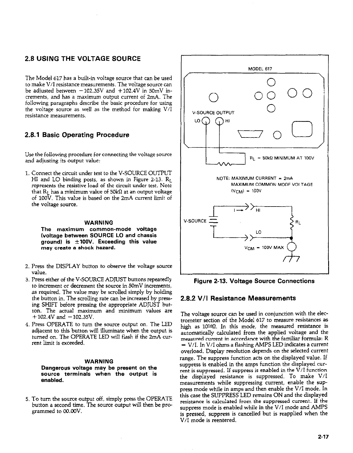
1. Connect the circuit under test to the V-SOURCE OUTPUT
HI and LO binding posts, as shown in Figure Z-13. RL
represents the resistive load of the circuit under test. Note
that RL has a minimum value of 5OkSl at an output voltage
of 1COV. This value is based on the 2mA current limit of
the voltage source.
WARNING
The maximum common-mode voltage
(voltage between SOURCE LO and chassis
ground) is +lOOV. Exceeding this value
may create a shock hazard.
2. Press the DISPLAY button to observe the voltage source
V&e.
3. Press either of the V-SOURCE ADJUST buttons repeatedly
to increment or decrement the source in 5ChnV increments,
as required. The value may be scrolled simply by holding
the button in. The scrolling rate can be increased by press-
ing SHIFT before pressing the appropriate ADJUST but-
ton. The actual maximum and minimum values are
+102.4V and -102.35V.
4. Press OPERATE to turn the source output on. The LED
adjacent to this button will illuminate when the output is
turned on. The OPERATE LED will flash if the 2nd cur-
rent limit is exceeded.
WARNING
Dangerous voltage may be present on the
sourca terminals when the output is
enabled.
5. To turn the source output off, simply press the OPERATE
button a second time. The source output will then be pro-
grammed to OO.OLW.
MODEL617
I
\
I
n
0:
V-SOURCE D”TP”T
0
LO
PP
HI
-0
0
\ I
/
RL = 50kR MlNlM”M AT loo”
NOTE: MAXlMLlM CURRENT = ZrnA
MAXIMUM COMMON MODE VOLTAGE
(“CM) = 1oov
Figure 2-13. Voltage Source Connections
2.8.2 V/I Resistance Measurements
The voltage source can be used in conjunction with the elec-
trometer section of the Model 617 to measure resistances as
high as lOWI. In this mode, the measured resistance is
automatically calculated from the applied voltage and the
measured current in accordance with the familiar formula: R
= V/I. In V/I ohms a flashing AMPS LED indicates a current
overload. Display resolution depends on the selected current
range. The suppress function acts on the displayed value. If
suppress is enabled in the amps function the displayed cur-
rent is suppressed. If suppress is enabled in the V/I function
the displayed resistance is suppressed. To make V/I
measurements while suppressing current, enable the sup-
press mode while in amps and then enable the V/I mode. In
this case the SUPPRESS LED remains ON and the displayed
resistance is calculated from the suppressed current. If the
suppress mode is enabled while in the V/I mode and AMPS
is pressed, suppress is cancelled but is reapplied when the
V/I mode is reentered.
2-17
 Loading...


